



Key Engineering Takeaways
- The LRS-200 body is 215 × 115 × 30 mm; it does not define the complete installation envelope.
- Check door-mounted protrusions against the assembled supply, wiring and support in all three axes.
- The example’s 10 mm overlap exists only where the two assemblies also overlap in the panel plane.
- Geometric margins do not establish cooling, electrical clearance or service acceptance; verify these requirements separately.
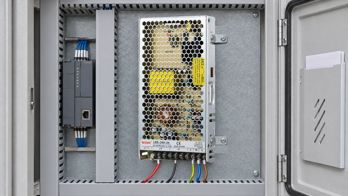
Why can a power supply fit the drawing but obstruct the cabinet?
A supply can fit inside its allocated rectangle while a door-mounted part collides with its conductors, protective cover or support when the door closes. For an OEM panel designer, the decision is whether the assembled, wired and maintainable installation fits, not simply whether the metal enclosure clears the panel boundary.
This article uses the LRS-200-24 enclosed power supply as the product reference. It provides a planning worksheet and review sequence; the numerical layout below is a hypothetical example, not a validated installation or a customer case.
What does the LRS-200 outline actually establish?
The published outline establishes a nominal enclosure size of 215 × 115 × 30 mm. The LRS-200 specification and dimension drawing is the source for that geometry. Check that the supplied unit, selected suffix and applicable drawing correspond before freezing a panel layout.
For the worksheet, define X and Y along the enclosure’s 215 mm and 115 mm sides, with Z representing its 30 mm thickness. These are drawing coordinates, not an instruction to install the unit in a particular orientation. An approved mounting orientation, tolerances and equipment conditions remain separate requirements.
The same sheet includes side and bottom fixing callouts, with M4 markings and L values of 5 mm and 3 mm respectively. Treat these as details to reconcile with the exact drawing and assembly instructions. They do not establish a complete fastener selection, tightening torque or permission to use every visible case screw as a mounting point.
The drawing also shows a 135 mm span between the mounting rows; the 115 mm body width does not describe all projecting mounting features.
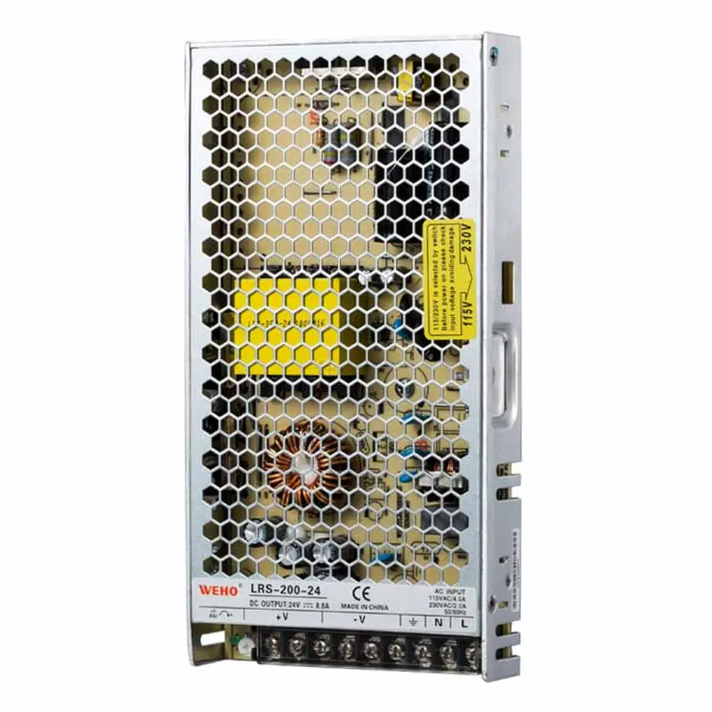
The photographed LRS-200-24 identifies the 24 V variant. Its appearance helps match the purchased unit to the layout; it does not prove usable ventilation clearance, mechanical strength or operation inside the finished cabinet.
How should the installed envelope be divided?
Divide the installation into separately checked space requirements rather than adding one undocumented clearance around every side. The enclosure, conductor route, thermal surroundings and access path answer different questions. A design can pass one check while failing another.
| Space requirement | What to record | Release evidence |
|---|---|---|
| Enclosure and fixing | Outline, hole locations, support and mounting orientation | Applicable LRS-200 drawing and the equipment mounting design |
| Connections | Terminal access, actual conductor route, termination and cover | Selected connection hardware and approved wiring layout |
| Thermal surroundings | Air path, neighboring heat sources and applicable load conditions | Model-specific instructions and equipment thermal verification |
| Door and obstacles | Door-mounted parts, duct covers and other occupied volumes | Assembly model checked in relevant open and closed positions |
| Service access | Tool approach, cover removal and product withdrawal route | A documented service sequence demonstrated on the intended assembly |
Connections deserve their own envelope because the end of the metal case is not necessarily the end of the installation. Conductor size, termination style, bend requirements and strain management depend on the selected parts and equipment design. Do not choose a bending radius from the photograph or pull conductors tight to make the cabinet drawing work.
Thermal space also requires its own review. An open geometric gap does not demonstrate the necessary airflow, and a neighboring heat source can matter without touching the supply. Obtain the applicable installation and operating limits; do not convert the planning margins below into a derating curve or a generic ventilation rule.
What does a 270 × 160 mm planning area leave available?
A hypothetical 270 × 160 mm rectangular area leaves 55 mm along X and 45 mm along Y after subtracting the published enclosure outline. If the enclosure is centered, the arithmetic divides those remainders equally. It does not establish that the resulting arrangement is suitable.
Hypothetical Panel-Space Planning Example
Assume that the panel designer has reserved an unobstructed X–Y rectangle measuring 270 × 160 mm. Place the 215 × 115 mm enclosure outline in that same plane, without rotation. This example contains no measured cabinet, wiring assembly or thermal test.
| Planning item | Calculation | Result | Meaning |
|---|---|---|---|
| Enclosure footprint | 215 mm × 115 mm | 24,725 mm² = 247.25 cm² | Nominal outline area only |
| Reserved planar area | 270 mm × 160 mm | 43,200 mm² = 432 cm² | Hypothetical design allocation |
| Remaining X dimension | 270 − 215; then 55 ÷ 2 | 55 mm total; 27.5 mm each side if centered | Geometric remainder, not required clearance |
| Remaining Y dimension | 160 − 115; then 45 ÷ 2 | 45 mm total; 22.5 mm each side if centered | Geometric remainder, not a wiring allowance |
| Area outside enclosure | 43,200 − 24,725 | 18,475 mm² = 184.75 cm² | Distributed space, not one usable rectangle |
| Depth before door obstruction | 90 − 45 | 45 mm available | Assumed backplate-to-door distance minus assumed inward protrusion |
| Depth outside bare enclosure | 45 − 30 | 15 mm | Geometry only; no connection or thermal approval |
| Assumed assembled interference | 55 − 45 | 10 mm overlap | Assumed 55 mm installed envelope intersects the door obstruction |
The distinction between area and access matters. The remaining area is distributed around the enclosure; it cannot be treated as an interchangeable pool of space. A terminal approach may require space at one end, while a door obstruction may consume depth above a different location.
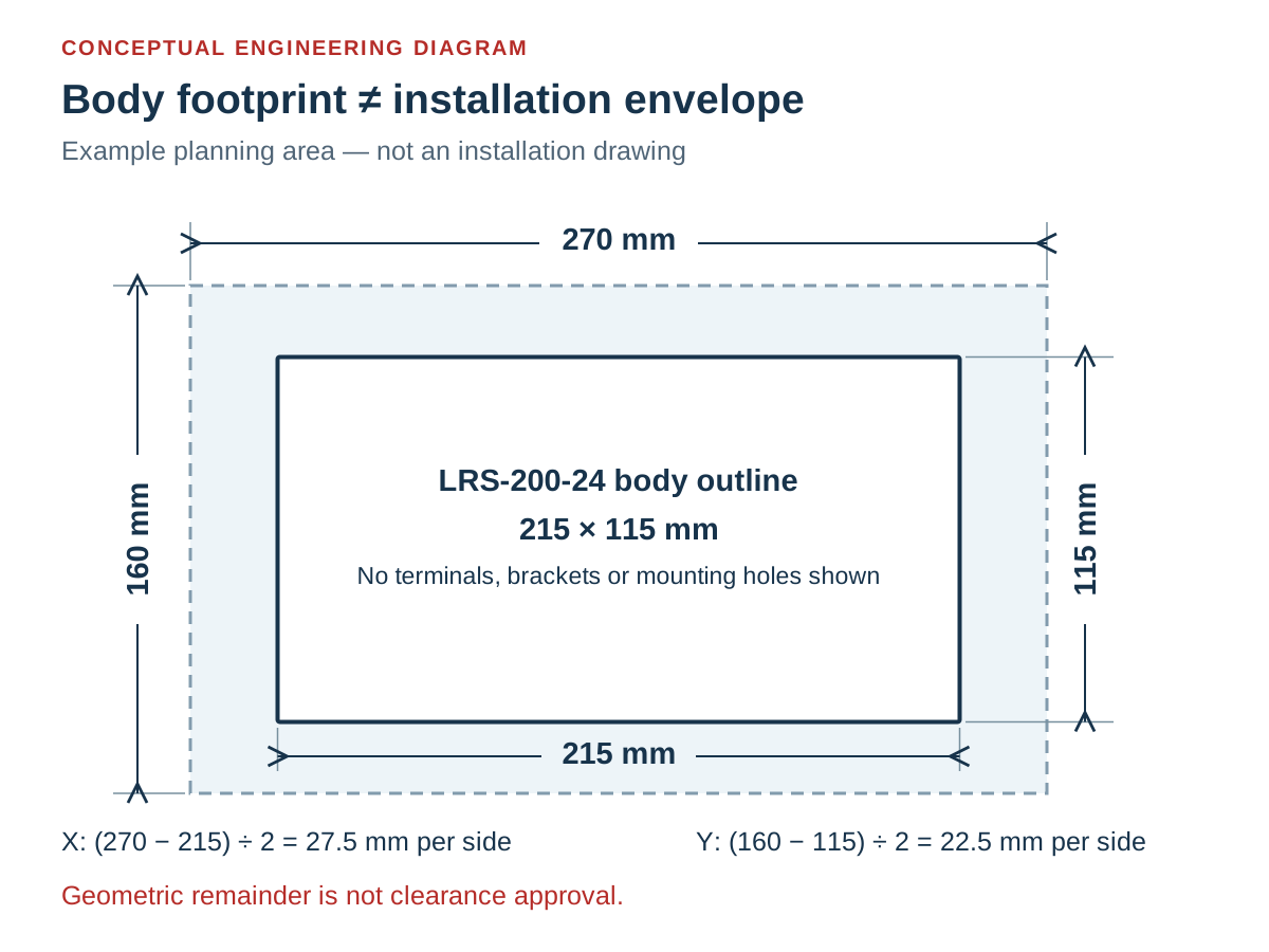
Swipe horizontally on a small screen, or open the full-size diagram.
Why can the closed door invalidate a flat layout?
The door can consume installation depth even when the panel footprint is clear. For a separate hypothetical Z check, assume 90 mm from the backplate to the closed door’s inner surface. Assume a door-mounted part projects inward by 45 mm and overlaps the supply’s planned X–Y area. It leaves 45 mm before that obstruction.
With the enclosure’s rear datum assumed at the backplate, its 30 mm thickness leaves a geometric remainder of 15 mm. Now assume the complete installed envelope, including its selected connections and support, reaches 55 mm from that datum. Because the two occupied volumes overlap in X–Y as well as Z, the resulting interference is 55 − 45 = 10 mm. The bare enclosure fits; the assumed assembly does not.
The 90 mm, 45 mm and 55 mm values are hypothetical design inputs, not WEHO dimensions or clearance requirements. Check the actual door sweep, protective covers, service movement and thermal conditions separately. For drawing-to-panel checks, use the OEM mounting-drawing review process alongside this space worksheet.
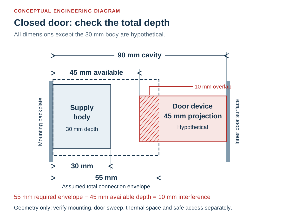
Swipe horizontally on a small screen, or open the full-size diagram.
How should an OEM verify the layout before panel release?
Verify the layout with the actual component geometry, planned connections and documented maintenance sequence. Record what was checked and the evidence supporting acceptance. Missing model-specific limits should trigger a technical query or a layout revision, rather than an invented pass value.
- Match the purchased configuration. Record the exact model, applicable drawing and supplied-unit identification. Reconcile substitutions and revision differences before drilling or releasing production files. Compare the LRS-200-24 product and drawing reference with the proposed assembly; a similar enclosure is not sufficient identification.
- Check support and fixing. Overlay the applicable mounting geometry on the panel design and review its supporting structure. Record the selected attachment design and relevant instructions. Confirm the fastener details rather than translating a drawing callout directly into an assumed screw length or torque.
- Model the connection envelope. Include the actual conductor and termination choices, terminal protection and nearby duct covers. Record where conductors leave the supply and enter their routing space. Verify that assembly access and documented conductor requirements remain available without forcing or obstructing the connections.
- Review the full cabinet geometry. Check door-mounted components, cable entries and other obstacles in their relevant positions. Record the limiting locations and usable space in X, Y and Z. Repeat this check after changes to the door hardware, wire duct or neighboring equipment.
- Separate thermal verification. Record the intended loading, ambient conditions, mounting orientation and neighboring heat sources. Check these against the applicable model documentation and equipment verification plan. Do not use a successful mechanical fit as a thermal acceptance result.
- Demonstrate the service route. Under the equipment’s appropriate isolation and maintenance procedure, verify the planned tool approach, cover removal and product withdrawal sequence. Qualified personnel should follow the equipment’s energy-control requirements; this worksheet does not prescribe energized work or a universal discharge waiting time.
Keep the resulting evidence with the panel revision. A useful release record identifies the enclosure drawing, wiring arrangement, access demonstration and remaining technical questions. If a later change occupies any of those spaces, reopen the affected checks instead of carrying forward an earlier approval without review.
What should you send WEHO for a cabinet-fit review?
Send the exact model requirement together with the panel allocation and the constraints that determine fit. Include the planned mounting arrangement, neighboring equipment, connection approach, door obstructions, load and ambient conditions, and maintenance route.
Ask WEHO to review your layout with those details and request the applicable installation information. Keep any unresolved mounting or operating requirement visible in your equipment release process. A dimensional enquiry is more useful when it shows the complete installation than when it supplies only the cabinet’s outside dimensions.
Engineering FAQ
Can I use the 30 mm enclosure thickness as my cabinet depth allowance?
The published 30 mm thickness describes only the enclosure, so it does not define the required cabinet depth. The installation also occupies space for its support, connections, protection and access. Check the assembled geometry and moving obstructions in the same coordinate system before accepting the cabinet depth.
Are the example 27.5 mm and 22.5 mm margins required clearances?
The 27.5 mm and 22.5 mm values are hypothetical geometric margins, not manufacturer clearance requirements. They do not specify thermal, electrical or service clearances. The relevant component instructions and equipment design must determine whether the space is suitable.
Does unused panel area prove there is enough room for wiring?
Unused panel area alone cannot establish wiring fit because the space must lie along the actual connection route. Check the actual terminal approach, selected conductor requirements, cover access and routing arrangement. Keep the connection envelope distinct from the metal enclosure outline.
Can a matching hole pattern establish that a replacement fits?
A matching hole pattern cannot establish replacement fit because other mechanical and electrical interfaces may differ. Compare the complete enclosure, terminal locations, protection, support, operating requirements and service route. Recheck the relevant electrical conditions separately before treating another model as a replacement.



