Key Engineering Takeaways
- A regulated converter's input current can increase as its input voltage falls.
- Solve feeder voltage and input current together when that effect matters.
- Treat constant power and efficiency as stated approximations, not universal behavior.
- Check startup, input limits and dynamic stability separately from the steady calculation.
Why can a fixed-current cable calculation underestimate DC input loss?
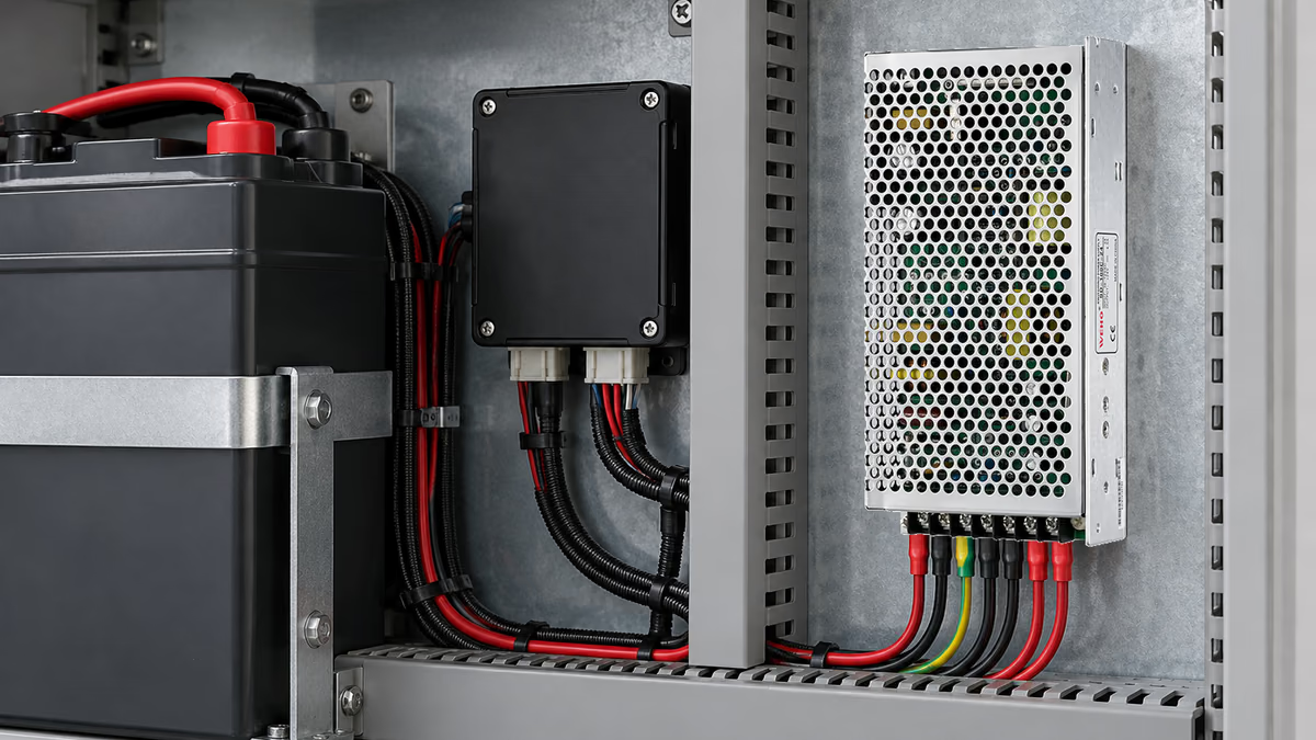
A regulated DC-DC converter may draw more input current as feeder voltage falls while it maintains the same output power. Using current calculated at the source voltage can therefore underestimate the drop along a resistive feeder. The decision is whether the complete source and harness leave an acceptable operating point at the converter terminals.
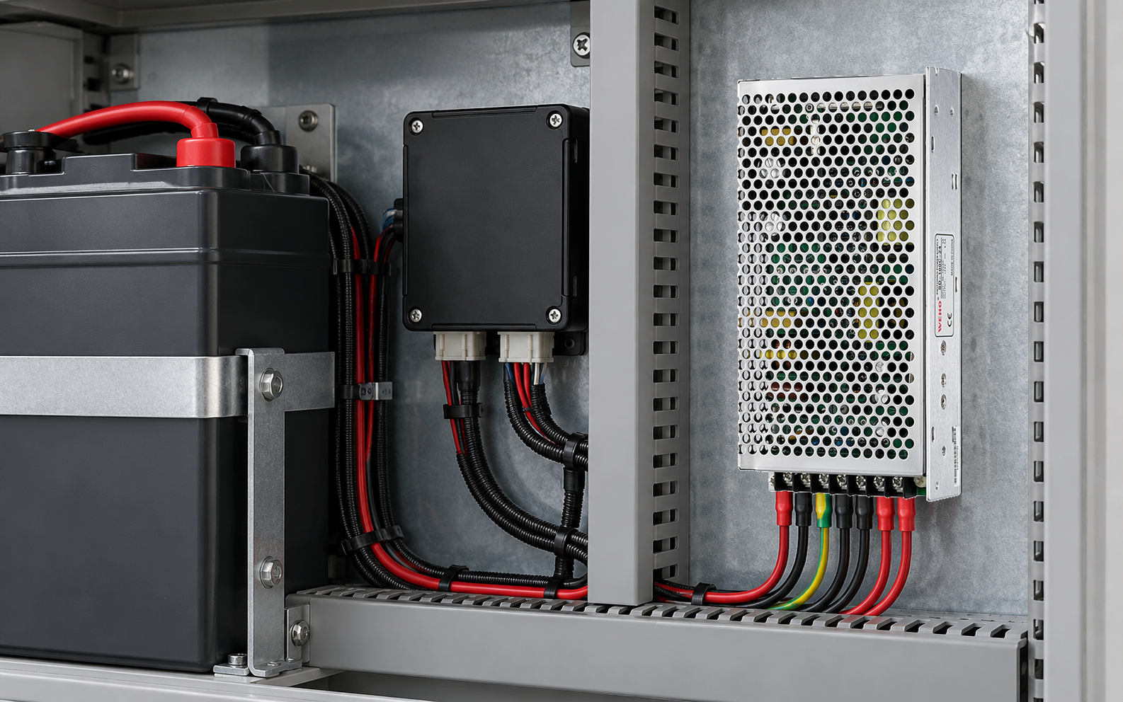
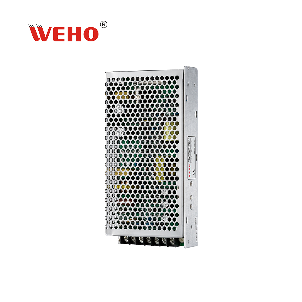
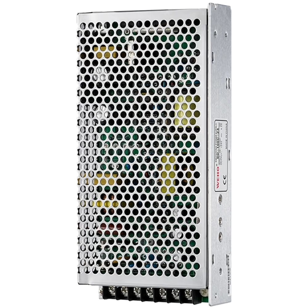
Der SD-100 DC-DC product reference includes different input versions and output options. The family is relevant to a DC-fed equipment discussion, but a family photograph does not select an input suffix. Match the ordered version to its applicable documents before using any input boundary in a release calculation.
This article calculates an illustrative steady operating point. It does not evaluate a BMS reconnect transient, authorize connecting a particular battery or claim that the converter behaves as a constant-power load in every state.
How do you solve voltage and current together?
For a fixed output power and assumed constant efficiency, input power is Pin = Pout / η. If the source voltage is Vs, the converter input voltage is Vc and the complete feeder-loop resistance is R, then Vc = Vs − IinR and Iin = Pin / Vc.
Substituting the second relationship into the first gives Vc² − VsVc + RPin = 0. The equation follows from the stated model; it is not a converter control law. Real efficiency, input protection and source behavior can differ from these assumptions.
Standard Engineering Sizing Example
Assume a hypothetical 24.0 V source, 90 W output demand, 90% efficiency and 0.40 Ω total feeder-loop resistance. Input power is 90 W / 0.90 = 100 W. The equation becomes Vc² − 24Vc + 40 = 0.
The higher-voltage mathematical solution is (24 + √416) / 2 = approximately 22.20 V. Input current is 100 W / 22.20 V = approximately 4.505 A. The feeder drop is about 1.802 V, and its resistive loss is I²R = approximately 8.12 W.
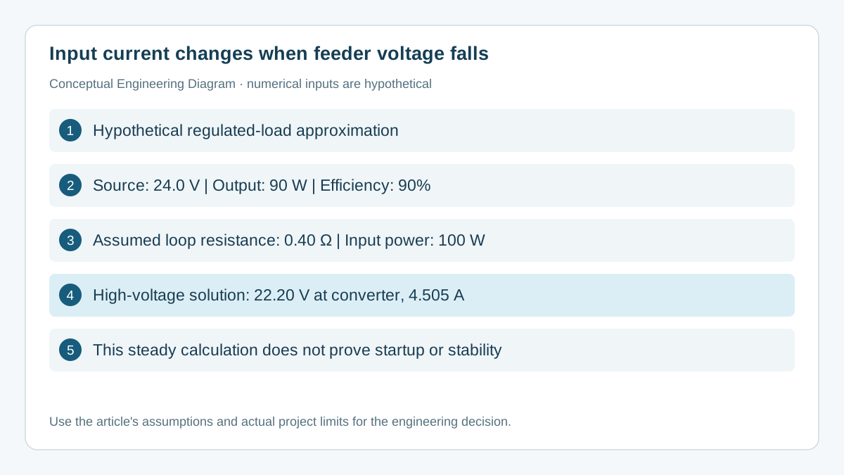
A source-voltage-only estimate gives 100 W / 24 V = 4.167 A, suggesting a 1.667 V drop. That estimate is lower because it does not account for the increased current at the converter's reduced input voltage. The complete solution is useful when the difference could change a design decision.
The quadratic also has a lower-voltage mathematical root. Do not treat either root as evidence of a usable or stable real operating state. The chosen converter's input limits, source current limiting and dynamic behavior still govern operation, and the constant-efficiency approximation may fail far from the intended range.
Which assumptions need an explicit record?
Record the source condition, resistance boundary and power requirement before comparing harness options. A battery's nominal label is not its minimum operating voltage. Loop resistance includes the intended forward and return paths, connectors and other series elements within the calculation boundary.
| Model input | Hypothetical value | Actual evidence required | Why it matters |
|---|---|---|---|
| Source voltage | 24.0 V | Voltage at the defined source terminals | Changes available headroom |
| Output demand | 90 W | Required operating load | Determines input power |
| Effizienz | 90% | Applicable operating-point evidence | Changes input current |
| Loop resistance | 0.40 Ω | Harness and contact condition | Sets feeder loss and heat |
These values are not SD-100 specifications. A constant efficiency is a simplifying assumption, particularly during startup, light load or near protection thresholds. If an efficiency curve or accepted measurement is available, use the value appropriate to each candidate operating point and document the calculation method.
Resistance can change with conductor temperature and contact condition. Include the specified equipment environment and plausible service variation. A calculation based on a short room-temperature bench cable does not establish the result for a longer production harness inside a warm enclosure.
How should an OEM verify the proposed feeder?
Verify source voltage, converter-terminal voltage and input current in the same operating state. Measuring only the source terminals misses the drop that the calculation is intended to evaluate. Keep source and converter reference points identifiable in the test record.
- Identify the exact input version and permitted operating conditions from the applicable SD-100 documentation. Define the equipment load and source range.
- Establish the feeder boundary, conductor routing, contacts and protection elements. Record the basis for the loop-resistance value.
- Calculate candidate operating points with clearly stated assumptions. Check converter input limits, harness ratings and source capability separately.
- Measure the representative assembly at the required source and load conditions using the approved procedure. Compare calculated and measured voltage, current and feeder heating.
- Evaluate startup and required load changes separately. Record current limiting, cycling or recovery behavior rather than assuming the steady equation predicts them.
If the source enters current limiting, the constant-voltage-source assumption no longer describes the system. If the converter stops regulating or reaches a protection boundary, the constant-output-power assumption may also cease to apply. Update the model or use the observed state; do not force the original equation to explain behavior outside its assumptions.
Opening a battery disconnect or inserting a current meter can change the circuit and create a new connection event. Use suitable instruments, energy isolation and the equipment's approved measurement procedure. This article does not specify a generic fuse, conductor size or live connection sequence.
What does this calculation leave unresolved?
A steady resistive calculation does not prove dynamic stability, filter compatibility or immunity to interruption. Cable inductance, capacitance, control response and source behavior can matter during changing conditions. Address those topics with the applicable documentation and an appropriate time-domain or impedance-based evaluation.
Likewise, an acceptable input voltage does not prove output capacity at every temperature or installation orientation. Use the SD-100 input-version and operating documentation for the ordered version. Keep thermal limits, output loading and protection coordination as distinct acceptance items.
The useful engineering output is a feeder worksheet that connects source conditions to the converter's actual terminal conditions. That worksheet can support a comparison between a shorter cable, a lower-resistance connection or another documented input version without pretending that any one change automatically qualifies the complete machine.
What should you send WEHO for a DC feeder review?
Send source minimum and maximum voltage, required output power, operating cycle, feeder-loop resistance or harness details, and measured converter-terminal voltage when discussing the SD-100 DC-DC supply options. Request the documentation for the proposed input and output combination before approving the assembly.
Engineering FAQ
Does every DC-DC converter draw constant input power?
No. Constant power is an approximation for a regulated output supplying a fixed demand over a suitable operating region. Startup, light load, current limiting and protection states may behave differently. State the approximation and verify its relevance.
Why not calculate input current at the battery's nominal voltage?
That is a useful first estimate, but it can miss feeder loss and source variation. When input voltage at the converter falls, maintaining the same output power can require more current. Evaluate the actual terminal condition.
Does the higher-voltage quadratic root prove stability?
No. It is a mathematical solution of the assumed steady model. Dynamic stability, startup behavior and documented operating limits require separate evidence. Do not label a root as a qualified operating point without those checks.
Can the example's 90% efficiency be used for an SD-100 purchase?
No. It is a hypothetical input. Use the relevant product evidence or accepted measurements at the actual operating conditions. Efficiency can vary with input voltage, output load and temperature.
Will increasing cable size always solve the problem?
Lower feeder resistance can reduce drop and loss, but the source, contacts, protection and converter must still meet their requirements. A wiring change can also affect connection transients. Recheck the complete affected assembly.