An AC ripple reading and a total RMS reading describe different quantities. Before rejecting a DC supply, identify the meter mode, frequency response and measurement points.
- AC-only RMS describes the alternating component within the instrument's usable response.
- AC+DC RMS includes the DC level and can conceal a small ripple difference.
- A meter number cannot replace a specified peak-to-peak oscilloscope test.
Why can two correct meters show different values?
Two meters can disagree because they measure different parts of the signal. One may reject the DC component in its AC mode; another may report combined AC+DC RMS. Even two AC-only instruments can disagree when their frequency responses, crest-factor limits or coupling arrangements differ.
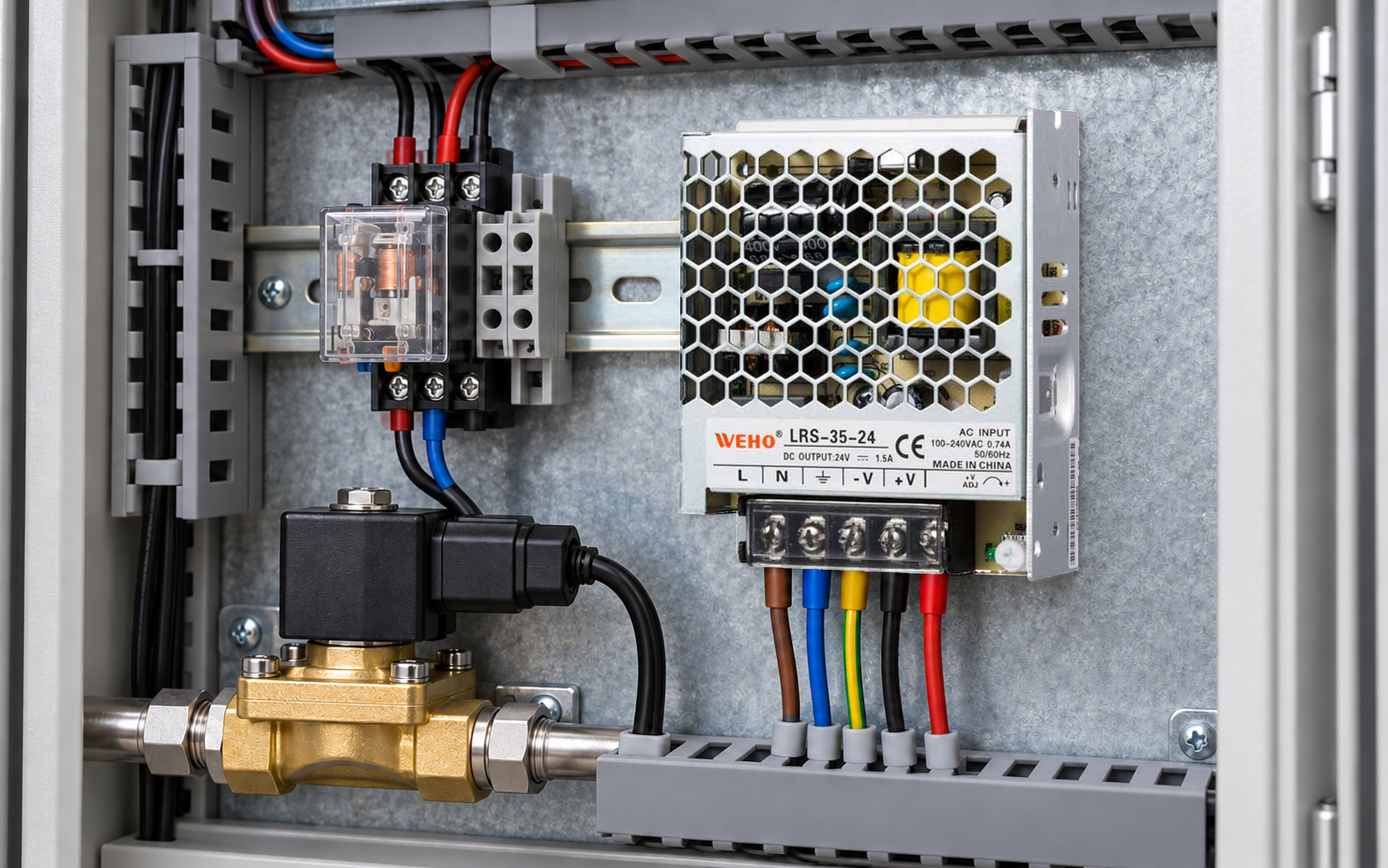
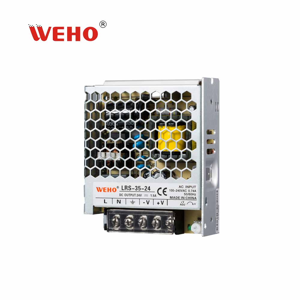
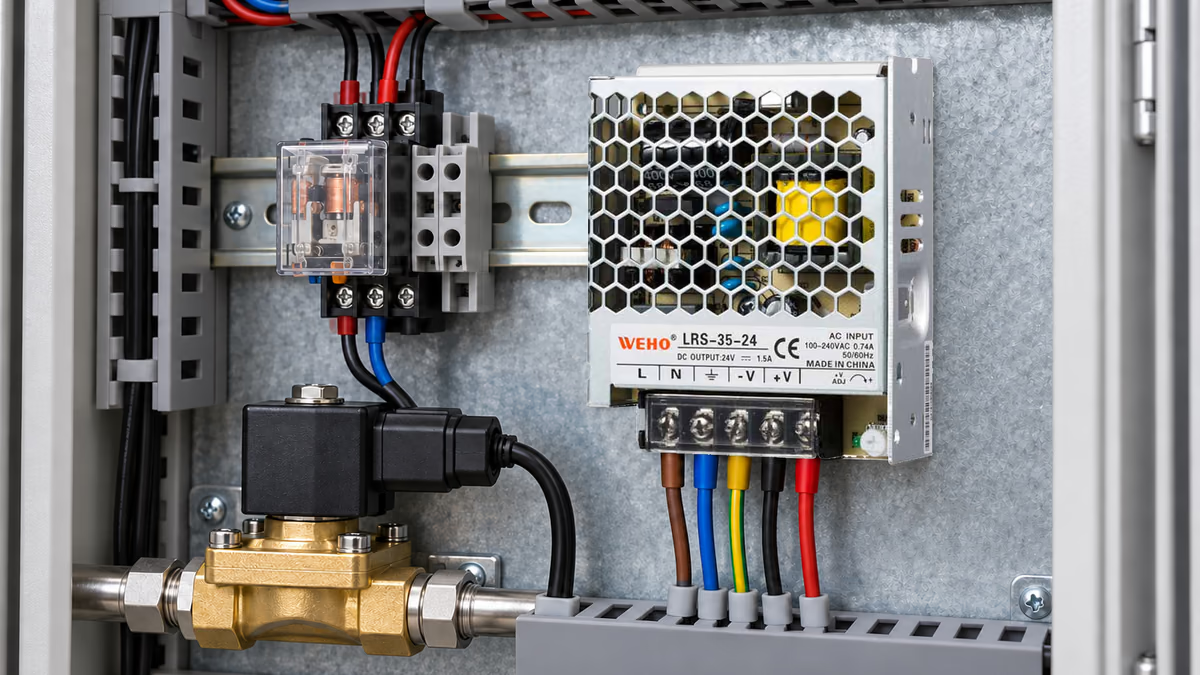
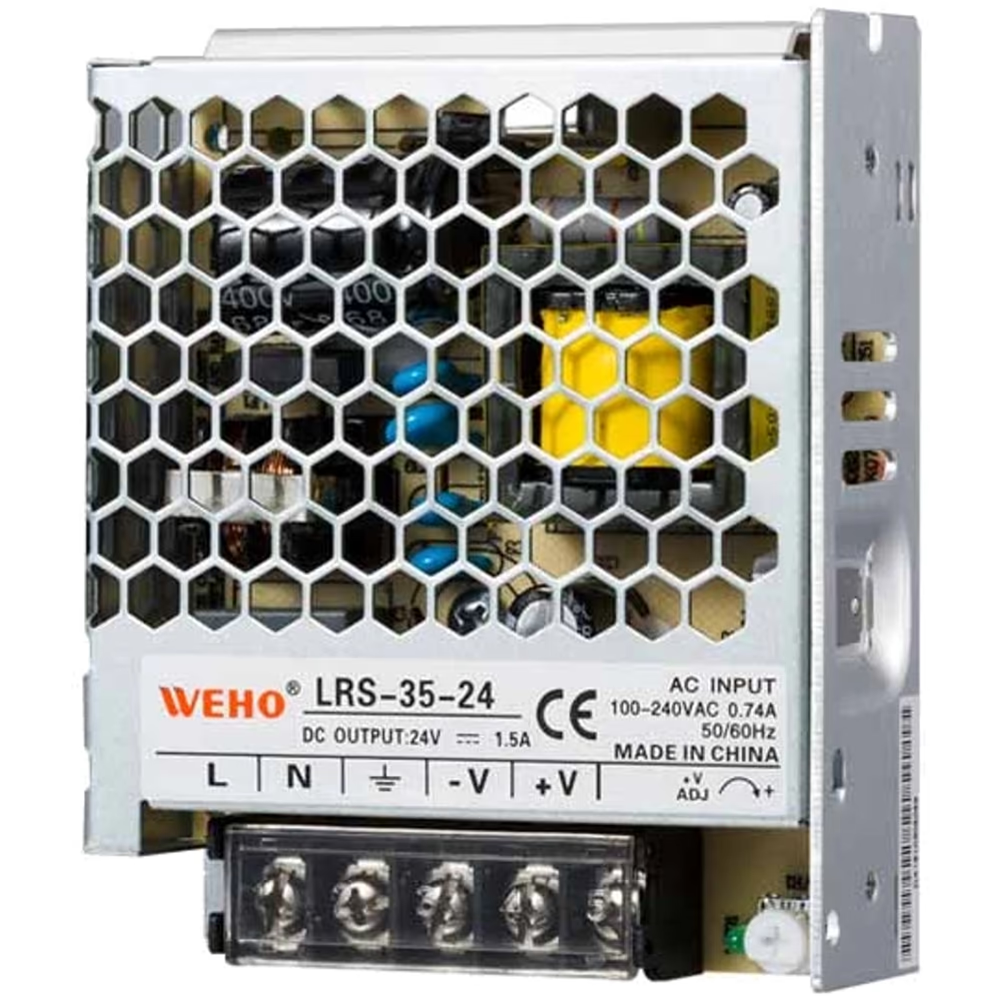
For an OEM evaluating the WEHO LRS-35 supply family, the first decision is whether the test addresses a load's electrical requirement or merely compares instrument displays. The pictured LRS-35-24 identifies the product context. It does not provide a measured ripple result.
A purchasing report that says only “ripple: 24 V” cannot establish excessive ripple on a nominal 24 V output. The number may be a DC or combined RMS measurement. Conversely, a small AC display does not prove that short switching spikes meet a peak-to-peak limit.
Define the acceptance quantity before comparing suppliers. Include AC RMS, total RMS, peak-to-peak voltage and any measurement bandwidth as separate fields when the project needs them. Do not convert among those fields without knowing the waveform and the instrument's response.
What is the mathematical difference?
For a waveform expressed as a constant DC component plus a zero-mean AC component, total RMS is the square root of the sum of their squared RMS values. This identity concerns the same observation interval; it does not guarantee that a particular meter captures all relevant frequencies.
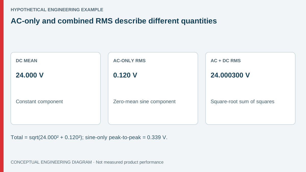
Consider a hypothetical output with a DC mean of 24.000 V and a sinusoidal AC component of 0.120 V RMS. The combined value is:
Vtotal,RMS = √(24.000² + 0.120²) = 24.000300 V, approximately.
The AC component adds only about 0.300 mV to the combined reading. A total-RMS display can therefore remain near 24.000 V while an AC-only mode reports 120 mV. Neither number alone tells the reader the manufacturer's specified ripple-test result.
If the example AC component really is sinusoidal, its peak-to-peak amplitude is 2 × √2 × 0.120 = 0.339 V. That conversion stops being valid for an arbitrary pulse train, switching spike pattern or mixture of frequencies. These inputs are illustrative calculations, not LRS-35-24 specifications or test data.
| Reported quantity | Example result | What it answers | What it cannot establish |
|---|---|---|---|
| DC mean | 24.000 V | Average output level | AC ripple amplitude |
| AC-only RMS | 0.120 V | Heating-equivalent AC component in the measured band | Uncaptured spikes or arbitrary peak-to-peak voltage |
| AC+DC RMS | 24.000300 V | Combined effective value | Small ripple directly from the displayed digits |
| Peak-to-peak | 0.339 V for this sine only | Maximum-to-minimum excursion | General conversion from an unknown waveform |
Which instrument details belong in the test record?
Record the exact instrument model, selected function, range and coupling setting. The words “true RMS” are insufficient because an instrument can calculate true RMS accurately only within its stated signal and operating limits. Check the applicable manual rather than assuming identical behavior across a brand's product range.
The usable frequency band matters when the DC output carries switching-related components. An AC mode designed primarily for mains-frequency work may attenuate much faster content. A lower display can reflect reduced response rather than a quieter supply. A wider-band instrument can also include interference that the specified acceptance method deliberately excludes.
Record the low-end AC accuracy and resolution. A meter can have an impressive voltage range while being a poor choice for a small AC component riding on a much larger DC level. Check maximum permitted DC in AC mode and the manufacturer's treatment of AC coupling.
Also define the connection points. Measuring directly at the supply and measuring at a remote load answer different questions. Cable impedance, load switching and environmental pickup can change the observed signal. A supplier comparison needs matched points and conditions, not merely the same output voltage setting.
How should an OEM run a useful comparison?
Begin with the actual load requirement and the applicable supply test method. If that method specifies an oscilloscope bandwidth, probe arrangement or added test network, reproduce it where appropriate. A handheld reading can provide a supplementary observation, but it should not silently replace the defined method.
- Identify the supply variant and the applicable output condition.
- Stabilize the intended input, load and ambient state before comparison.
- Document DC mean, AC-only RMS and instrument mode separately.
- Capture the waveform with suitable equipment when peak excursions matter.
- Repeat at the receiver only when assessing the complete distribution path.
Qualified personnel should establish the test setup with the required isolation and guarded access. A grounded oscilloscope reference can create an unintended connection; never remove protective earth to obtain a convenient waveform. Probe ratings and common-mode capability must suit the circuit.
Keep the same connection geometry when changing instruments. Long pickup loops or moving reference points can create differences unrelated to the supply. If a second instrument produces a different number, first check what changed in the measurement system before adjusting the output or rejecting the sample.
What should the supplier receive?
Send a concise evidence record containing the acceptance quantity, instrument function, measurement location and operating state. Include waveform files if the dispute concerns spikes, intermittency or timing. A screenshot of a meter display without its mode and test context is usually insufficient for reproducing the observation.
Der LRS-35 product information provides the starting point for identifying the relevant family. Request the applicable variant documentation for the order and compare it with the test record. Do not assume the family photograph establishes a bandwidth, ripple limit or receiver compatibility.
Useful escalation questions are specific: Was the reading AC-coupled? Which frequencies could the instrument capture? Was the load steady? Was the result taken at the supply terminals or across a receiver? These questions can distinguish a measurement disagreement from a reproducible electrical issue.
For the oscilloscope side of the review, Tektronix's power-supply probing application note explains why probe configuration and reference arrangements need attention. Use the instrument documentation for the actual setup; the external note does not establish a WEHO product limit.
Include the instrument's residual reading with an appropriate reference condition when the required AC signal is near its lower usable range. Do not subtract that number automatically: instrument noise and an actual signal do not always combine as simple signed offsets. The comparison needs the method appropriate to those contributions.
When sharing a waveform, preserve the acquisition interval as well as bandwidth. A brief maximum observed once and a continuously present periodic component lead to different receiver questions. Describe both when the record contains them, rather than reducing an intermittent event to a single RMS label.
Prepare an LRS-35-24 measurement review
Send WEHO the intended load condition, required ripple quantity, instrument models, connection photograph and available waveform record. Identify the exact supply variant and the document used for acceptance. This gives the technical discussion a reproducible starting point and keeps an instrument-mode difference from becoming an unsupported product conclusion.
Häufig gestellte Fragen
Does true RMS mean every ripple frequency is captured?
No. True-RMS processing remains subject to the instrument's bandwidth, amplitude, crest-factor and range limits. Check those limits for the selected function and signal instead of treating the front-panel wording as a universal accuracy statement.
Can AC RMS be converted directly to peak-to-peak ripple?
Only when the waveform relationship is known and applicable. The sine-wave conversion used above cannot be applied automatically to switching spikes or mixed waveforms. Measure peak-to-peak voltage using the defined test arrangement when that is the acceptance quantity.
Is a total RMS reading close to 24 V evidence of low ripple?
It is not enough. A small alternating component changes the combined RMS value very little when the DC component is large. Use a suitable AC-only function and waveform measurement to answer the actual requirement.
Should the output voltage be adjusted until the meters agree?
No. First resolve the mode, bandwidth, location and operating-condition differences. Output adjustment changes the DC operating point and may create a receiver compatibility problem without resolving the measurement discrepancy.