Redundancy does not automatically make a power supply hot-swappable. A redundant system may keep a load powered after a source fails. Replacing a module while the host remains energized additionally requires a designed interface, a permitted service procedure and evidence that removal, insertion and recovery do not violate the equipment’s limits.
On this page
- Separate fault survival from live service
- Write the live-service boundary explicitly
- Check the state before the next removal
- Treat insertion as its own electrical event
- Approve the service states, not just the steady bus
- Verify that redundancy is actually restored
- State the service requirement when requesting a supply
For an OEM defining a serviceable machine, the question is not only “does the remaining capacity cover the load?” It is also “which part may be handled, under which live conditions, and what proves the complete service event is acceptable?”
Separate fault survival from live service
The existing WEHO N+1 design guide addresses capacity, isolation, sharing and fault boundaries. Use that work as the prerequisite. This article adds the service qualification: what happens when a module is deliberately removed or introduced, including when another source is already unavailable.
TDK-Lambda’s redundancy white paper treats hot swapping as replacement with the system input and output remaining on, using appropriate interfaces and connectors. That description does not permit live work on ordinary exposed supply terminals. The replaceable module, rack or host assembly and the intended service action must be identified together.
Write the live-service boundary explicitly
A host can remain powered while a permitted module is locally disabled or isolated before removal. Record those distinct states instead of using “live” to describe the entire assembly. Identify the exact module, connector, backplane, isolation arrangement, interlocks and monitoring revision covered by the procedure.
Do not infer permission from a removable handle, a parallel-use statement or an ORing stage alone. Likewise, a protective hot-swap controller is not a complete personnel-safety or connector qualification. The system manufacturer’s supported assembly and procedure determine what the operator may do.
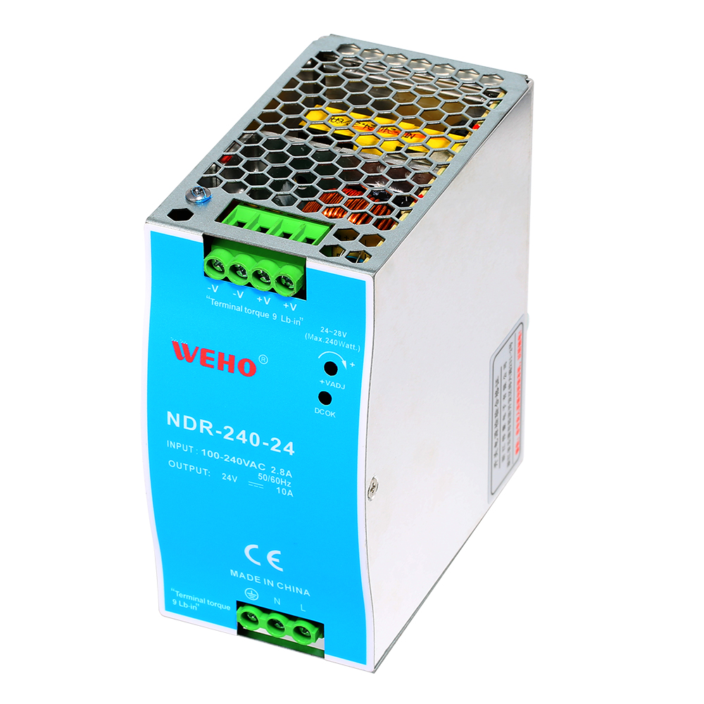
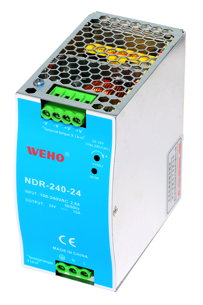
Consider the WEHO NDR-240-24 as a concrete boundary check. Its product identity and NDR-240 documentation concern a DIN-rail supply; the front photograph identifies the enclosure, model and visible terminals. Those items do not establish a hot-swap connector, permitted live removal or supported insertion into an energized system. Keep live service unresolved unless the exact assembly and manufacturer procedure explicitly cover it.

| Service question | Required decision or evidence |
|---|---|
| What remains energized? | Host input, common output bus and the state of the selected module |
| What may be removed? | Exact replaceable part and mechanically compatible interface revision |
| What prevents an unacceptable event? | Documented isolation, insertion management and permitted connector/service sequence |
| Who may act? | Qualified service role, access controls and the manufacturer’s procedure |
| What proves restoration? | Load continuity, module contribution, alarms and recovered redundancy |
Check the state before the next removal
Assume a hypothetical 14 A critical load and three modules, each already qualified for 8 A usable contribution under the project’s conditions. All three offer 24 A. With one unavailable, two offer 16 A, which exceeds the stated load. That is only the assumed capacity calculation; it does not demonstrate dynamic behavior or live-service permission.
If one module has failed and a second healthy module is then removed for service, only 8 A remains. The original one-failure capacity claim has not disappeared, but it does not cover this different state. The service plan must prevent that action or provide a separately qualified alternative.
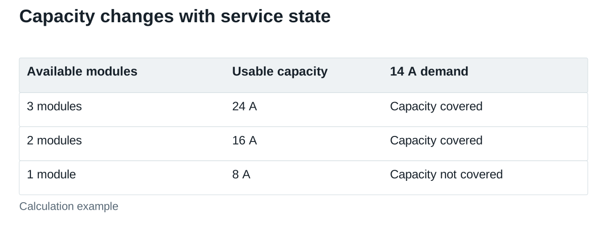
Account for the actual operating load before allowing an action. Equipment options, changed cooling conditions or temporary startup demand can change the available margin. An operator should not infer restored redundancy merely because the common bus voltage is normal.
Treat insertion as its own electrical event
TI’s hot-swap explanation discusses current and voltage disturbances when modules join a powered host, and the possible placement of protection on the module or backplane. Its examples are device-design context, not a circuit prescription for an industrial supply.
For the selected assembly, request the allowed initial conditions and insertion controls. Determine how the incoming module’s capacitance, output setting, enable state and sharing function are handled by the documented design. Do not invent a connector sequence or external component arrangement to make an unsupported supply “hot swap.”
Define the load’s allowed voltage excursion and interruption time. A module entering the rack successfully does not prove that a controller downstream avoided reset or that another source stayed within its current limit. Use a test method that can capture the relevant event rather than relying on a steady final voltage.
Approve the service states, not just the steady bus
| Controlled state | What to observe | Acceptance record |
|---|---|---|
| One module unavailable | Remaining contribution, bus voltage and load function | Capacity and operating limits remain satisfied |
| Permitted removal sequence | Selected-module state, load transient and alarms | Procedure and continuity requirements are met |
| Permitted insertion sequence | Bus excursion, source currents and protection response | No unacceptable disturbance or unintended protective trip |
| Module recovery | Current contribution, sharing and status indications | The system reaches its defined restored state |
| Invalid or inhibited action | Specified interlock or service-control response | An unsupported action is prevented as designed |
Agree input, load, thermal and configuration conditions before testing. Repeat the permitted action for every relevant slot or path when their behavior differs. Use the responsible manufacturer’s safe service instructions and qualified personnel; this table does not authorize handling exposed energized parts or bypassing an interlock.
Verify that redundancy is actually restored
After replacement, check that the new module is contributing as intended, not merely present or showing a green indicator. Confirm the expected sharing or standby behavior, clear the relevant alarm through the approved method and verify that monitoring recognizes the restored number of available sources.
Record the removed and installed identities, firmware or configuration where relevant, the event outcome and any required follow-up. A mixed revision may require a compatibility check even when the nominal voltage and power match. An unresolved alarm or unavailable spare path must remain visible to operations.
State the service requirement when requesting a supply
Ordinary WEHO AC-DC documentation must not be treated as hot-swap approval without exact supporting evidence. Send the proposed model, host architecture, critical-load states and intended replacement action. Distinguish requirements that can tolerate a planned shutdown from those that demand a manufacturer-supported live-service assembly.