



Last Updated: October 1, 2026
Quick Answer: An encapsulated power supply protects its conversion circuitry within a filled or sealed assembly rather than leaving the electronics exposed behind a ventilated cover. For B2B LED installations, selection still depends on the exact electrical model, thermal path, mounting and external connections. WEHO describes its XLG family as fully glued in an aluminum IP67 housing. The XLG-150-24 provides a documented 24 V, 6.3 A example, but its 180–264 VAC input and conflicting dimensional heading require ordered-revision checks. Encapsulation is not permission to ignore heat, installation protection or service access.
What Does Encapsulation Change?
An OEM choosing an encapsulated power supply is making an environmental and serviceability decision, not merely choosing an enclosure style. A filled assembly can reduce exposure of internal electronics to contaminants. Its suitability for moisture, vibration and temperature nevertheless depends on the actual construction and documented qualification. An attractive aluminum case alone does not establish the internal process or a particular test result.
Ο WEHO product catalog specifically describes XLG as fully glued, with an aluminum case and IP67 protection. Those statements support discussing an encapsulated family. They do not identify the compound chemistry, prove unlimited immersion, establish pressure-wash resistance or authorize opening the unit. This guide therefore does not depict an invented internal cutaway or assign unverified silicone, epoxy or polyurethane properties.
Start With an Exact Electrical Model
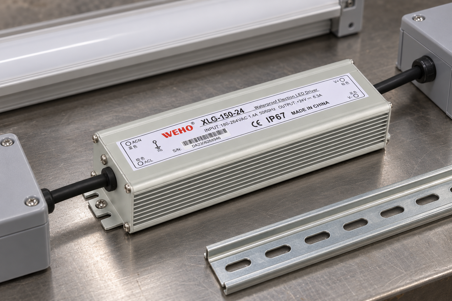
Ο official XLG-150 product page includes different output-voltage versions. A procurement description such as “waterproof 150 W driver” cannot replace a full model. For the verified XLG-150-24 example, the photograph shows INPUT 180–264 VAC, 1.4 A, 50/60 Hz and OUTPUT +24 V, 6.3 A. The supplied specification also lists 180–264 VAC input. Do not describe this as universal 100–240 V mains acceptance.
The family is nominally 150 W. Multiplying the documented 24 V and 6.3 A gives 151.2 W, which the product page lists for this version. That arithmetic is not a guarantee of unrestricted full-load operation in every sealed cabinet. Confirm the delivered revision, environmental limits and approved operating duty. Nor should the page’s broad constant-current wording be treated as proof of dimming, an adjustable current control or compatibility with any LED module.
Build a Load Schedule Before Ordering
For a hypothetical 24 V linear-lighting system, a concurrent 120 W load draws 120 ÷ 24 = 5 A. This example is below both the nominal 150 W family value and the model’s 6.3 A listed current. It is a screening calculation, not a prescribed design margin or an actual measurement from either pictured application.
List the LED segments and any control electronics supplied by the unit. Check their simultaneous operation, startup behavior, voltage tolerance and permitted supply type. Determine the far-end voltage after conductor and connector losses. Long runs may require a different distribution design rather than increasing the supply voltage. A published current rating does not remove those load-compatibility checks.
Use the project’s verified input voltage for selection. A 230 V AC design can be evaluated against the stated 180–264 VAC range; a 120 V AC project cannot simply reuse this model. Any conditional ratings or revision differences must be resolved before the bill of materials is approved.

Evaluate the Thermal Path, Not Just the Seal
A sealed assembly still creates heat while converting power. The engineering task is to provide a suitable path from the housing to its surroundings and keep the project within the exact revision’s operating limits. The verified source shows a finned aluminum body without a fan, ventilation openings or adjustment controls. Do not depict wires entering imaginary vents or claim that the absence of a fan eliminates thermal constraints.
Assess mounting-surface material, contact, surrounding temperature, nearby heat sources and duty duration. Avoid wrapping the case in insulation or placing it against a hot process surface. An extra enclosure can change cooling conditions, even when it improves protection of external wiring. Seek a model-specific derating confirmation where the available evidence does not establish continuous load at the intended temperature.
Keep Mechanical Axes and Connections Clear
The specification table, mechanical drawing and separate dimension image show a 190 mm overall length, 49 mm case width and 34 mm thickness. The enclosure body is 166 mm long within that mounting envelope. However, the supplied PDF also contains a conflicting 170 × 49 × 34 mm heading. This guide uses the agreeing 190 mm references and flags the discrepancy; the ordered revision must be confirmed before cabinet release.
The real product has screw-mount end flanges, with six R2.1 slot positions shown by the mechanical drawing. It has no DIN-rail clip. A neighboring 35 mm rail is a scale reference for other cabinet components, not an adapter for this supply. Allocate additional room for cable bends, protected joints and access; exterior dimensions are not installation-clearance instructions.
Fixed input and output leads exit opposite ends. The documented input is line, neutral and protective earth; the output is positive and negative. Preserve identification, polarity and the source’s actual exit geometry. The sealed housing does not automatically protect a splice, gland, junction box or downstream luminaire. Protection of the complete installed circuit remains a separate design responsibility.

Match the Environment Without Overstating Evidence
A pedestrian-underpass maintenance box and an industrial inspection-light service compartment illustrate two different lighting contexts. Both images show the corresponding supply on a support plate during de-energized servicing. They are illustrative layouts, not proof that a particular installation was commissioned or that its measured load equals the worked example.
For the wash-zone context, the service plate is kept outside direct spray. IP67 on the product label is not a system-level washdown certification. Confirm the cleaning process, enclosure access, cable entries and external joints rather than assuming the product rating covers every installed component.

Compare Sealed and Vented Options Deliberately
A sealed, fully glued family may fit a documented environmental requirement; a vented supply may offer a different mounting format, access arrangement and thermal design. Compare exact WEHO models using the product guide and their own drawings. Do not transfer another family’s input range, mounting holes or protections into the XLG specification.
For service planning, treat the encapsulated unit as an assembly rather than promising component-level repair. Record the full replacement model, ordered revision, lead arrangement and mounting envelope. Before energizing, qualified personnel should verify isolation, protective earth, polarity, external protection, load compatibility and acceptable voltage at the luminaires. Preserve the commissioning record and the revision-specific operating limits.
Key Takeaways
- Select an exact full model, not a generic waterproof wattage description.
- XLG-150-24 evidence supports 24 V, 6.3 A and 180–264 VAC input; 150 W is the nominal family designation.
- Use the 190 × 49 × 34 mm references with an explicit ordered-revision check because the PDF heading conflicts.
- Verify thermal duty, screw mounting and external connections separately from encapsulation and IP67.
Σύναψη
The right encapsulated supply balances documented environmental protection with electrical fit, heat removal and maintainable installation. XLG-150-24 is a source-supported example for qualifying 24 V LED projects, not a universal recommendation. Give WEHO the actual mains, load schedule, enclosure conditions and required mechanical revision before approving the order.
Συχνές Ερωτήσεις
What is an encapsulated power supply?
It uses a filled or sealed assembly to protect conversion electronics rather than leaving them exposed behind a ventilated cover. Confirm actual construction, electrical ratings and environmental qualification; a metal housing alone does not establish a specific encapsulation process.
What evidence supports XLG as an encapsulated family?
WEHO’s official product catalog describes XLG as fully glued with an aluminum IP67 housing. This supports discussing encapsulation without assigning an unverified resin chemistry, internal cutaway, immersion duration or pressure-wash capability.
What input and output are documented for XLG-150-24?
The exact source photograph shows180-264VAC,1.4A,50/60Hz input and+24V,6.3A output.150W is the nominal family designation;24V times6.3A is151.2W. Qualify the ordered revision, load compatibility and thermal duty; this is not a universal-mains model.
Why is the190mm dimension qualified?
The specification table, mechanical drawing and separate dimension image agree on190mm total length,49mm case width and34mm thickness, with166mm body length. The same PDF has a conflicting170mm heading, so confirm the ordered revision before mechanical release.
Can XLG-150-24 mount directly on DIN rail?
The evidenced product has screw-mount end flanges and no DIN-rail clip. Its mechanical drawing shows six R2.1 slot positions. A nearby35mm rail in the illustrations is an adjacent-component scale reference only.
Does IP67 protect the complete lighting installation?
No. External splices, glands, junction boxes, luminaires and cleaning exposure need independent project checks. This guide keeps the industrial service compartment outside direct spray and does not claim system-level washdown certification.




