



Verify the passive probe and oscilloscope channel together before assigning a rounded edge or apparent overshoot to a power supply. An incorrectly compensated divider can distort the displayed transition even when the applied voltage has no overshoot.
Key engineering takeaways
- Match the probe's compensation range to the actual channel.
- Keep compensation, attenuation scaling and calibration distinct.
- Check a suitable reference before interpreting a DUT transition.
- Preserve the original capture and the corrected measurement setup.
Which part of the measurement might create the shape?
An OEM validation engineer needs to decide whether an unexpected peak belongs to the equipment or to its measurement chain. The observation should first be recorded as a displayed waveform. Calling the first peak “power supply overshoot” assigns a cause before the probe, channel and reference have been checked.
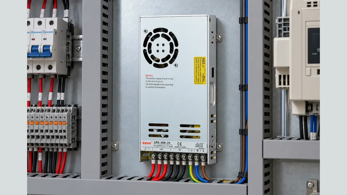
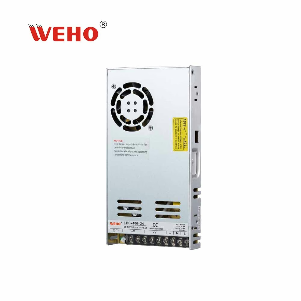
For an LRS-400-24 waveform review, retain the full supply identity, operating state and actual voltage node. The product photograph identifies the candidate supply. It does not establish the waveform, the installed harness response or the suitability of a particular probe.
Compensation concerns the probe-channel response, while the equipment's permitted voltage excursion concerns the actual electrical event. Correcting the instrument setup is therefore part of obtaining usable evidence, not permission to relax a receiver limit. The original questionable record should remain available with the reason it was superseded.
Why does an attenuating passive probe need compensation?
A simple attenuating probe combines resistive and capacitive paths. Their relative division should agree over the frequency range for which the system is intended. A mismatch can make the displayed edge lead or lag its eventual plateau, changing both apparent amplitude and shape.
NI's probe-selection guidance explains the importance of resistance, capacitance and bandwidth, including individual probe-channel compensation. Check the actual combination rather than assuming that a probe remains correctly adjusted after moving it to another channel or instrument.
Compensation is also different from entering the attenuation ratio in the channel menu. A wrong ratio can scale all reported voltages incorrectly. A correct ratio does not flatten an incorrectly compensated response, and a flat reference does not establish that the numerical attenuation setting is correct.
A simplified divider can produce a false peak
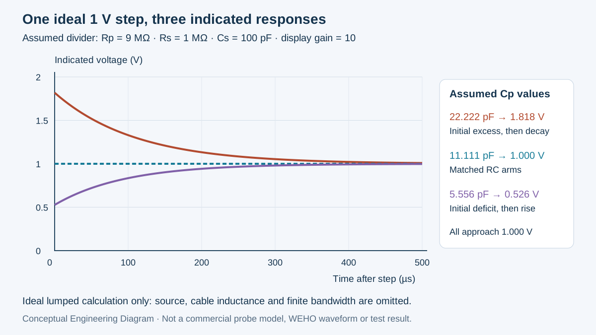
Consider a hypothetical lumped divider, not the internal design of a commercial probe. Let its upper arm be Rp = 9 MΩ in parallel with Cp, and its lower arm be Rs = 1 MΩ in parallel with Cs = 100 pF. Assume an ideal zero-impedance source, a unit voltage step and no other circuit elements.
The model's DC transfer is Rs/(Rp + Rs) = 0.1. Assume the displayed value multiplies the divider output by ten, so the final indicated level is 1.000 V for the 1 V input. Frequency-independent division in this model requires Rp × Cp = Rs × Cs, giving Cp = 11.111 pF, rounded.
For the ideal step's initial capacitive division, the raw ratio is Cp/(Cp + Cs). The scaled initial indication is therefore 10 × Cp/(Cp + Cs). A capacitance that is too large makes this initial value exceed the final level; a capacitance that is too small makes the initial value fall below it.
| Assumed Cp | Upper-arm RC | Scaled initial indication | Final indication |
|---|---|---|---|
| 5.556 pF, rounded | 50 µs | 0.526 V | 1.000 V |
| 11.111 pF, rounded | 100 µs | 1.000 V | 1.000 V |
| 22.222 pF, rounded | 200 µs | 1.818 V | 1.000 V |
Swipe horizontally on a small screen, or open the full-size diagram.
The input in every row is the same ideal 1 V step. The last row's apparent excess is 1.818 − 1.000 = 0.818 V, approximately 81.8% of the final level. That exaggerated result demonstrates the assumed divider mismatch; it is not a plausible-error guarantee or an LRS-400-24 test result.
For this model, the indicated step is 1 + (A0 − 1) × exp(−t/τ), where A0 is the scaled initial value and τ = (Rp × Rs/(Rp + Rs)) × (Cp + Cs). The three settling constants are 95, 100 and 110 µs respectively. With matched arms, the exponential coefficient is zero, so the idealized response is flat.
The model deliberately omits distributed cable behavior, inductance, source impedance, finite rise time and bandwidth limits. Its calculation explains a causal mechanism, not a procedure for constructing or modifying a probe. Real limits and adjustment methods come from the actual probe and oscilloscope documentation.
What does the reference check establish?
Ο Tektronix P6106A instructions describe checking compensation before critical amplitude or rise-time work, and show undercompensated, overcompensated and appropriately adjusted reference responses. Their instrument-specific adjustments are not universal commands for every probe. Use the instructions and suitable reference for the installed equipment.
A reference check tests a defined response under its own conditions. It does not independently establish every bandwidth, voltage, loading or calibration property of the complete measurement chain. Record the reference source and the settings used, including the probe attenuation mode and the oscilloscope input configuration.
Keysight's passive-probe user guide provides another manufacturer's example of matching a passive probe to an input channel. A probe whose compensation range cannot accommodate that channel should not be accepted merely because the trimmer has reached an endpoint. Resolve compatibility against the specified equipment combination.
| Observation | What it supports | What remains separate | Record needed |
|---|---|---|---|
| Reference top changes after compensation | Probe-channel adjustment affected the displayed response | Actual DUT voltage behavior | Before/after reference and configuration |
| Voltage changes by a constant scale factor | Attenuation configuration needs checking | Frequency-response compensation | Hardware mode and channel scaling |
| Ringing changes with the return connection | Measurement-loop effects need investigation | RC compensation and DUT behavior | Connection arrangement and comparable traces |
| Adjusted reference is acceptable | The documented reference check passed | All other instrument and DUT acceptance requirements | Applicable criterion and its measured scope |
Do not collapse every distorted edge into the same diagnosis. Ground-path inductance, probe loading, bandwidth and a real electrical transient can coexist with compensation error. Establish the connection and energy-reference requirements before attaching instruments; compensation cannot make an otherwise unsuitable ground connection acceptable.
This article addresses divider response after a suitable measurement arrangement has been selected. Connection planning and compensation remain separate decisions.
Verify, record and repeat the intended event
- Identify the complete combination. Record probe, attenuation mode, oscilloscope, channel, input impedance and applicable instructions. Verify the allowed combination, ratings and compensation range before accepting the setup for the intended node.
- Preserve the starting evidence. Save the original reference and DUT captures with their settings and operating states. Verify that filenames and timestamps distinguish an initial questionable trace from a later corrected measurement.
- Check the documented reference. Qualified personnel should follow the equipment's reference and adjustment procedure. Record the observed response and criterion; verify that the setting is supported rather than merely adjusted until an attractive waveform appears.
- Repeat the DUT event. Keep the relevant load, input, trigger, node and acquisition conditions comparable. Record the repeated result separately, and verify that a changed operating state has not been mistaken for an instrumentation improvement.
- Apply the real acceptance rule. Evaluate the valid waveform against the equipment's documented voltage-versus-time requirement. Hold a conclusion when the instrument response or event repeatability remains unresolved; retain the reason with the review record.
Prepare an LRS-400-24 transient enquiry
Send WEHO the LRS-400-24 candidate identity, actual load event, permitted receiver voltage and the appropriately acquired trace. Include the probe-channel reference record when measurement distortion is part of the question. Do not send only a cropped peak with no configuration or operating context.
Complete the probe-channel check, preserve both versions and repeat the intended event before assigning the cause. If the valid measurement still exceeds the equipment requirement, investigate that actual event through the responsible engineering process. A corrected instrument trace is evidence to interpret, not an automatic product approval.
Engineering FAQ
Does a correct attenuation ratio mean the probe is compensated?
No. Attenuation scaling and frequency-response compensation are separate settings. Check the hardware mode, channel scaling and documented reference response together, because a numerically correct scale can still display a distorted transition.
Can probe compensation remove genuine power-supply overshoot?
No. Compensation adjusts the measurement chain rather than the supply. It can remove a measurement artifact, but a validly measured excursion still needs comparison with the receiver requirement and investigation under the actual operating conditions.
Is a flat reference waveform a complete calibration certificate?
No. A reference compensation check has a defined scope and does not replace the instrument's applicable calibration or verification requirements. Preserve the reference conditions and identify what was actually checked instead of assigning unrestricted accuracy to the system.
Are the model's 81.8% excess and capacitances WEHO specifications?
No. They are deliberately exaggerated assumptions in an ideal divider example. The values explain how a capacitive mismatch can alter an indicated edge and must not be attributed to an LRS-400-24, a real commercial probe or a completed test.



