



- A photoelectric sensor’s sensing distance does not establish the smallest feature it can reliably detect.
- Check sensing mode, effective beam or spot at the target plane, part orientation and position tolerance.
- Use slits or apertures only for the exact sensor and accessory combination approved by its manufacturer.
- The C3Z-D100N reference supports a model-specific enquiry; no slit accessory or minimum target size is established here.
Why a large sample can conceal a small-feature problem
A packaging machine detects a complete carton during setup but misses a narrow tab on a changed package. The original test established detection of one large target under one arrangement. It did not establish whether the tab changes enough of the received light at every permitted orientation and lateral position.
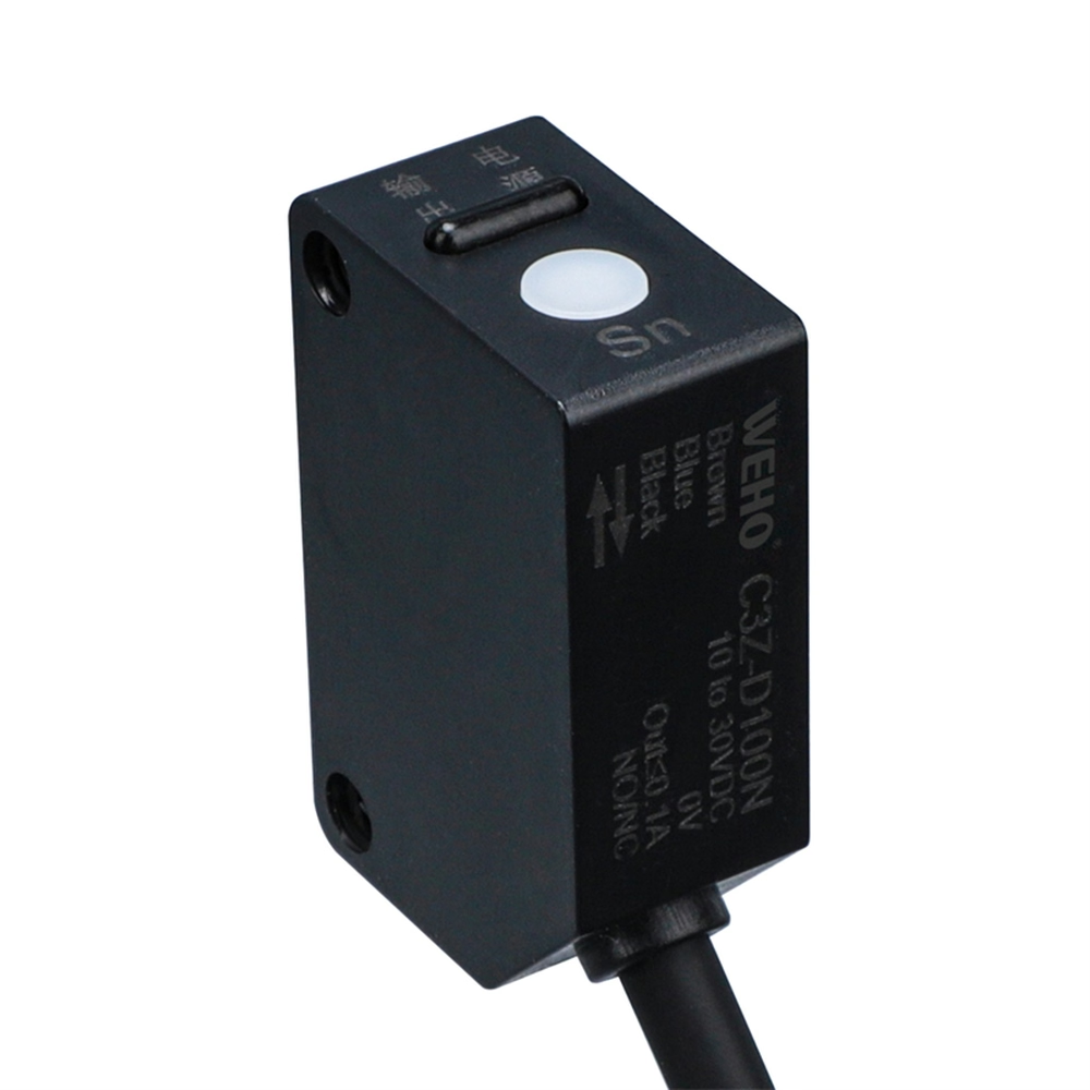
Ο WEHO C3Z-D100N product reference identifies a diffuse-reflective candidate and lists a white non-glossy standard target. That standard-target condition must not become an unstated minimum-object-size claim. Evaluate the actual feature and obtain the applicable model documentation before approving a small-part application.
Separate sensing distance from target geometry
Record the physical feature that must be detected, including its minimum manufactured width, thickness, surface and allowed orientation. A nominal dimension on a drawing may be larger than the projected dimension presented to the optical system. A nearby carrier, background or adjacent feature may also return light that the selected test did not isolate.
Identify the sensing mode before selecting a geometric model. A through-beam arrangement detects interruption between a separate emitter and receiver, while a diffuse-reflective arrangement receives light returned by the target. The same physical target can therefore require different trials and cannot inherit a detection limit from a different mode.
OMRON's photoelectric terminology guide treats standard sensing objects and minimum sensing objects as different specifications with stated conditions. Use that distinction when reviewing a quotation. Ask which target material, sensitivity setting, distance and travel direction support any proposed minimum-size figure.
An effective beam and the visible light pattern are also different concepts. Banner's photoelectric sensor overview distinguishes the working beam in interruption modes from the broader beam pattern. A visible spot on a sample is useful setup information, but its apparent outline alone is not a qualified switching boundary.
Use a simple coverage calculation as a screening check
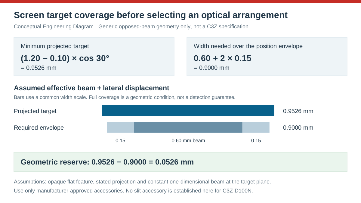
Consider an intentionally simplified one-dimensional interruption example using a generic opposed sensor pair. Assume an opaque rectangular feature has a width of 1.20 ±0.10 mm, an allowed projection angle of 30°, and lateral center displacement of ±0.15 mm. Assume a constant 0.60 mm effective beam width at the target plane; none of these values describe C3Z-D100N.
For this chosen flat-feature geometry, the minimum projected width is w_projected = (1.20 − 0.10) × cos(30°) = 0.9526 mm. To cover the assumed beam across the full lateral displacement, the minimum required target width is w_required = 0.60 + 2 × 0.15 = 0.9000 mm. The geometric reserve is only 0.0526 mm.
The reserve is a dimensional screening result, not a measured detection margin. The calculation assumes full beam interruption, a correctly defined target projection and no other displacement or optical effects. Reflectivity, translucency, beam shape, sensitivity and receiver behavior require separate treatment appropriate to the chosen sensing mode.
| Hypothetical effective beam | Width required with ±0.15 mm displacement | Reserve against 0.9526 mm target | Geometric screening decision |
|---|---|---|---|
| 0.40 mm | 0.7000 mm | +0.2526 mm | Full coverage fits the stated model |
| 0.60 mm | 0.9000 mm | +0.0526 mm | Small reserve; evaluate omitted variation |
| 0.80 mm | 1.1000 mm | −0.1474 mm | Full coverage cannot be assured by this model |
The table compares three assumed optical geometries; it is not a table of accessories or selectable settings for a WEHO sensor. A smaller required beam may prompt investigation of another approved sensor arrangement. It does not justify attaching a mask to the current sensor or claiming that a setting change creates the assumed width.
Swipe horizontally on a small screen, or open the full-size diagram.
Check whether a slit is an approved option
A slit or aperture can change the working beam for equipment designed to accept that accessory. OMRON's through-beam slit FAQ describes narrowing the optical path and explicitly excludes its discussed reflective sensor modes. This is guidance for the manufacturer's arrangements, not authorization to modify a different sensor.
Obtain the exact accessory part number, compatible emitter and receiver models, mounting instructions and revised sensing conditions. A package marked “photoelectric slit” does not establish compatibility with another housing or optical design. A mechanical fit can still obscure an optical element, alter received energy or change an environmental boundary.
The C3Z-D100N page reviewed for this article does not establish an approved slit or aperture combination. Keep its diffuse-reflective sample evaluation separate from the generic opposed-beam calculation above. If the actual feature is too small or its surface response is unsuitable, request an appropriate documented alternative rather than improvising an accessory.
Build trials around the smallest real feature
Prepare target samples representing the minimum feature dimension and the real surface variation, rather than testing only a larger white reference card. Include the permitted orientation and lateral positions from the mechanism drawing. Identify target specimens individually so an apparently successful setup can be reproduced after a material or tooling change.
Use fixtures that control distance and orientation without hiding the feature behind a different reflective surface. Record the sensor setting and the surrounding background for each arrangement. A result obtained with a temporary bright backing card belongs to that configuration and cannot silently qualify a production arrangement without the card.
Define the observable detection requirement before the trial. For example, require the expected state in every defined stationary target position and the expected absence state with the feature removed. The number of trials and decision rule must follow the project's risk and performance requirements; this article supplies no universal sample count or acceptable miss rate.
- Identify the optical task. Record the exact sensor suffix, sensing mode, target drawing and required presence decision. Accept the task definition when a reviewer can distinguish the feature from its carrier and background.
- Calculate the geometry. Record minimum projected dimensions and the complete position envelope at the target plane. Accept the screen only when the correct optical model and all stated allowances are visible in the calculation.
- Verify accessories. Request manufacturer confirmation for any proposed slit, aperture or optical attachment. Release an accessory only when its exact part number, compatible models and changed conditions are documented.
- Test actual targets. Capture results for the defined material, orientation and position cases using the approved setup. Record sample identity, settings and observations; accept only the cases supported by the pre-agreed decision rule.
- Freeze the configuration. Save photographs, drawings, sensor and accessory numbers and target material revisions. Require review when a change affects the optical geometry or the target surface presented to the sensor.
Keep the result limited to the tested configuration
A passed target-size trial establishes only the defined samples, settings and geometry. It does not independently establish position repeatability, high-speed counting, mutual-interference immunity or a safety function. Those tasks need their own requirements and evidence, even when the same sensor housing appears in the application.
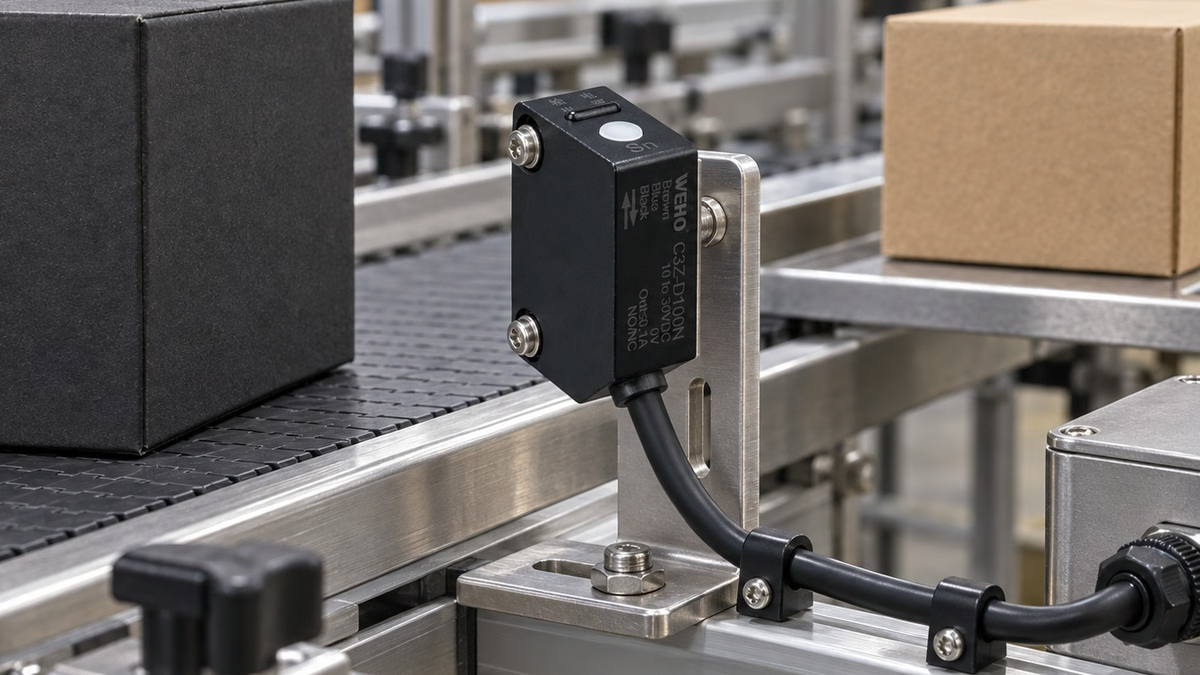
The application illustration shows an installed C3Z-D100N body, supported factory cable and conveyor context. Its cartons are not dimensional reference targets, and the image does not show a calibrated optical spot or a test outcome. Preserve that distinction when sending the article or a scene image to a purchasing team.
An enquiry should also separate target identification from output compatibility. Confirming an optical response does not establish the receiver wiring or application logic. Keep the complete sensor suffix and receiving-device requirements in the project record so the purchase order does not collapse different configurations into a family name.
Use the published C3Z-D100 setup guide for the broader target, mounting and receiver record. The present review adds a narrower decision: whether the smallest required feature and proposed optical geometry have sufficient documented support.
Prepare a C3Z-D100N small-target enquiry
Send WEHO the C3Z-D100N reference, a target drawing, the smallest feature dimensions, surface samples, distance and allowed position envelope. Ask which documented configuration can address the task and whether any optical accessory is explicitly approved. Use the WEHO contact page to provide the actual sample conditions before ordering an assumed equivalent.
Frequently asked questions
Does a long sensing distance mean the sensor detects very small objects?
No, sensing distance and minimum target size describe different conditions. Obtain the applicable target-size specification or evaluate actual samples at the required distance and orientation.
Can I fit a through-beam slit to C3Z-D100N?
No approved combination is established by the sources reviewed here. C3Z-D100N is identified as diffuse-reflective, so a different manufacturer's through-beam accessory instructions provide no permission to add a slit.
Does full geometric coverage guarantee a detection result?
No, full coverage closes only the stated geometric screen for an interruption model. Optical transmission, sensitivity, alignment and the actual sensor characteristics still require evidence.
Can a large white sample qualify a small dark feature?
No, those samples present different dimensions and optical properties. Use the smallest actual feature and relevant surface variation in the project-specific evaluation.



