For conventional light-intensity sensing, excess gain describes how much received light is available relative to the switching threshold in the supplier’s defined test conditions. A sensor that works at a clean, nominal distance may still have too little margin for the actual target, alignment changes or contamination.
Use optical margin to qualify a detection task
Margin alone does not prove reliable detection. Check both target-present and target-absent conditions, as well as the background, target variation and the actual detection mode. For any specific device, use the manufacturer’s definition and available evidence rather than assuming every photoelectric technology publishes a comparable excess-gain curve.
Banner Engineering explains excess gain as a relationship between received light and the level required for operation. Its curves and application recommendations describe its own devices and conditions, not an automatic specification for WEHO.
Start with a real sample and sensing mode
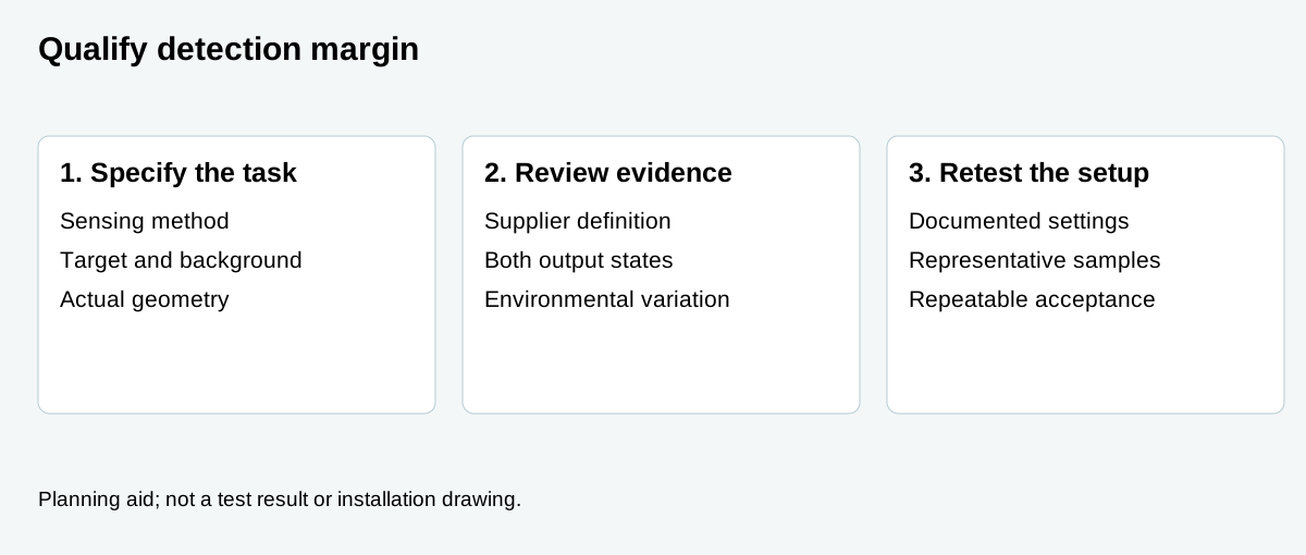
List the exact sensor version, whether the task uses through-beam, retroreflective, diffuse or another sensing method, and the required output state for target present and absent. Document working distance, angle, background, target surface and the range of actual parts. Detection distance alone does not capture that complete task.
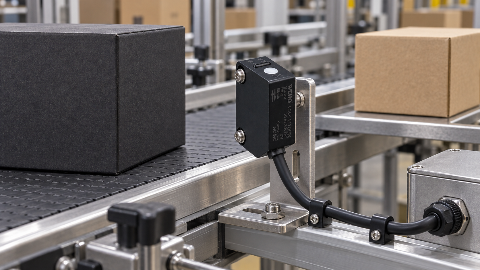
Ο WEHO C3Z-D100N page describes a diffuse photoelectric sensor. The manufacturer photograph identifies the product, while the lead image is an AI-assisted dry sample-validation illustration. Neither image establishes an excess-gain curve, a stability indicator or a specific margin. Ask for the correct performance information and sample validation method for the exact model.
Understand the threshold without inventing a number
In a conventional optical explanation, a received-light level near the switching threshold leaves little room for changing conditions. More signal relative to that threshold can provide margin against some reductions in received light. The supplier’s definition, target and test arrangement matter, so compare values only when their definitions and conditions are compatible.
An indicator is not necessarily a calibrated margin meter. OMRON describes a stability indicator for its own devices; do not assume another sensor has the same indicator, colors or threshold. A power lamp or output lamp by itself cannot quantify optical margin.
Protect both target and background decisions
In an interrupted-beam task, the receiver must reliably distinguish an unobstructed beam from the condition when the intended target blocks it. In a diffuse arrangement, the target and background produce different responses depending on geometry and surface. Raising sensitivity or optical signal without checking both states can change the separation between the desired target and an unwanted background.
Ask the supplier how its selected technology represents detection margin and what sample range is appropriate. Time-of-flight or background-suppression devices may not expose the same analog received-light ratio as a conventional excess-gain curve. Do not infer distance-setting accuracy or target immunity from a general optical formula.
Create a qualification matrix
| Condition | Test evidence | Decision |
|---|---|---|
| Target present | Representative samples, distance, angle and required output. | Is every relevant target detected? |
| Target absent | Actual background, guides and nearby reflective surfaces. | Does the output remain correct without the target? |
| Installation variation | Allowed position and alignment range, fixture tolerances. | Is there margin over the expected mechanical range? |
| Περιβάλλο | Expected contamination, cleaning and ambient conditions. | Can the approved maintenance plan retain reliable sensing? |
| Evidence and settings | Manufacturer documentation, settings, samples and results. | Can the approved setup be reproduced after replacement? |
This worksheet is a proposed equipment qualification record. It is not a measured excess-gain curve or a claim of verified performance for the pictured product.
Validate changes rather than selecting by range alone
Begin with controlled sample trials at the actual mounting position. Include product colors and finishes, background changes, acceptable target movement and the planned operating state. Record the cases that produce the least separation between correct target-present and target-absent decisions.
If margin is insufficient, discuss supported sensor, optical arrangement or mechanical changes with the supplier. After an adjustment, repeat both target states and any other affected detection positions. Keep environmental checks realistic: do not apply unapproved cleaning products or deliberately contaminate safety-critical machinery.
Questions buyers ask
Does a longer rated sensing distance guarantee a robust installation? No. The specified target, sensing mode, actual geometry, background and environment must also fit the task.
Does a bright indicator prove adequate excess gain? Not without the exact model’s indicator definition and the relevant validation conditions.
Is the highest sensitivity always best? No. Verify the desired target and the absence of unwanted background detections together.