A power supply EMC report does not by itself establish RF immunity of the equipment it powers. For conducted and radiated RF disturbances, match the report to the exact supply and tested arrangement, then define the complete equipment’s ports, operating modes and required behavior. Release the assembly against an agreed equipment-level plan, including functions that can fail while the DC rail still appears normal.
This guide helps OEM and EMC teams turn a broad request for “RF immunity” into a reviewable acceptance record. It does not assign a test severity to every industrial product or claim that a pictured WEHO model has passed a particular RF test.
Identify the disturbance and governing requirement
Emissions describe disturbance leaving equipment; immunity concerns its response to an applied disturbance. A conducted-emissions Class A or Class B result is therefore a different item from an RF immunity result. Analog Devices’ power-supply immunity overview separates radiated RF, conducted RF, ESD, EFT and surge references. Keep those phenomena distinct in the purchasing specification.
IEC 61000-4-3:2020 provides a basic method for radiated RF field immunity. IEC 61000-4-6:2023 concerns conducted disturbances induced by RF fields. Their official summaries place applicability, appropriate levels and performance criteria with the relevant product committees. Identify the product standard, edition and market requirements governing the actual equipment before selecting a program with the laboratory.
Write down the required frequency ranges, stress levels, modulation, exposure conditions and applicable ports. Do not copy another product’s range or criterion simply because both use an AC/DC supply. An EFT, ESD or surge pass addresses another disturbance method; the related EFT planning guide και ESD equipment-validation guide should remain separate records.
Separate supplier evidence from equipment acceptance
Ask for the complete supply report, including tested model, revision, loading, cables, enclosure, external filtering and observed performance. A statement such as “IEC 61000-4-6” without configuration and outcome cannot tell the integrator whether its application is covered.
Freeze the proposed equipment separately: supply and controller revisions, firmware, cable lengths and shields, bonding, enclosure openings, external interfaces and connected peripherals. Compare that arrangement with the supplier’s tested setup. Differences are review actions, not automatic failures or automatic approvals.
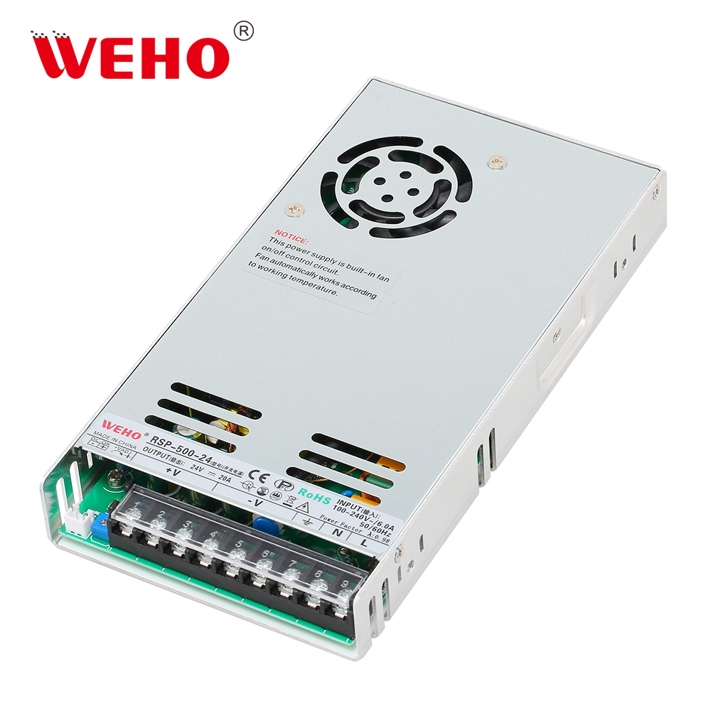
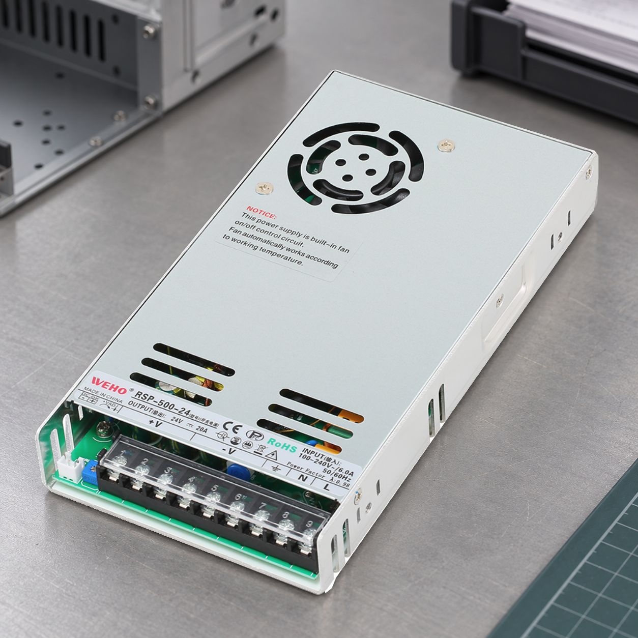
The pictured RSP-500-24 provides a traceable hardware identity for this discussion. Request its applicable current documentation and report before assigning it an immunity capability. The photo, a logo or a generic family specification does not fill that evidence gap. For emissions-report review, use the separate conducted-emission evidence checklist.
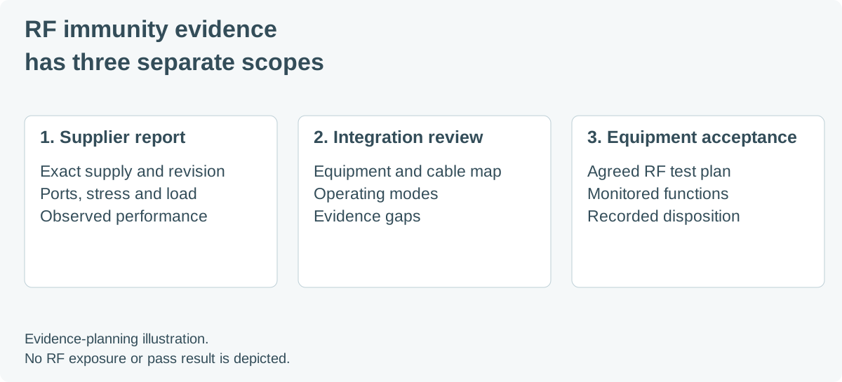
Create a port and operating-mode matrix
Organize the plan around the equipment’s real interfaces. A mains lead, an external DC port and a communication cable can have different roles in the agreed method. Do not treat every internal rail as an externally exposed port, or presume a port is exempt without the applicable basis.
On small screens, scroll sideways to compare each test scope with its evidence.
| Scope | Configuration and exposure to record | Functional evidence to agree |
|---|---|---|
| Conducted RF: supply interface | Applicable port, coupling method, supply source, load state, cable arrangement and required RF program. | Rail behavior and relevant equipment functions during exposure and recovery. |
| Conducted RF: signal or control interface | Actual connected peripheral, cable and shield arrangement, auxiliary equipment and monitoring connections. | Data integrity, command execution and acceptable error or interruption limits. |
| Radiated RF: equipment enclosure | Equipment faces and orientations, cabling, enclosure state and operating modes required by the agreed method. | Functions sensitive to exposure, including behavior that a front-panel indicator cannot reveal. |
| Mode transitions | Applicable acquisition, communication, standby or control transitions included in the test plan. | State retention, permitted intervention and recovery requirements defined in advance. |
| Repeat after a change | Revised filter, cable, bonding, hardware or firmware, with the repeat scope justified by the responsible reviewers. | Traceable comparison with the original finding and the remaining applicable tests. |
This is a proposed planning worksheet. The equipment’s governing requirements and laboratory method determine its final entries; it is not a report of a completed test.
Monitor the function that matters
Define observable success before exposure. Useful checks can include a measurement sequence counter, communication-error log, output-state readback and retained-configuration comparison. Choose indicators that correspond to the actual equipment task rather than adding measurements with no decision value.
Specify whether a temporary deviation is allowed, how it will be detected, what recovery means and whether operator intervention is permitted. If a product standard supplies performance criteria, map the equipment functions to those criteria. Avoid inventing one universal tolerance or recovery interval for every power supply and load.
A real ADI support question about conducted immunity describes lost RS-485 data during RF testing. It demonstrates a functional problem requiring investigation; it does not establish that the power supply caused it. In another TI high-frequency immunity discussion, the response asks for the end equipment and test expectations because evaluation-board results depend on the system.
Record an RF finding without guessing its cause
Consider a hypothetical measuring instrument that continues displaying a supply-status light while its acquisition sequence skips a sample during an RF sweep. Preserve the frequency or step identifier, mode, affected function, rail observations, logs and required criterion. If monitoring did not capture a rail event, record that limitation. Neither an illuminated indicator nor missing rail data proves that the supply was unaffected or responsible.
Use a common event reference so the laboratory record, application log and electrical observations can be compared. Have the laboratory review the observation arrangement; monitoring cables and auxiliary equipment must be identified as part of the setup. Distinguish a repeatable RF-related finding from an ordinary application fault before attributing a mechanism.
Close the evidence gaps before release
The release file should connect the exact equipment build to the adopted method, exposure program, configuration photographs, functional criteria, observations and disposition. Retain unresolved conditions and the reason for any limited scope. A successful investigation at one frequency or interface does not erase other applicable conditions.
When changing the supply or its installation, identify what changed and ask the responsible EMC reviewers which evidence remains applicable. Preserve the accepted configuration for later substitutions. The useful supplier contribution is a model-specific report and clear integration conditions, followed by equipment-level verification where required.