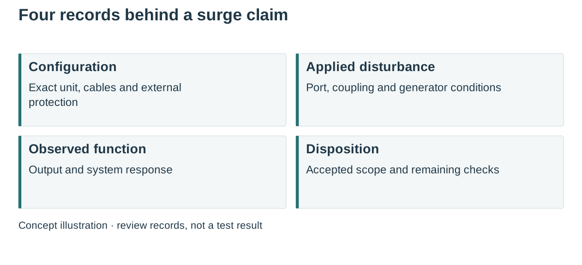
A surge immunity test report is useful only when its waveform, affected port, coupling mode, source impedance, operating state and acceptance criterion match the question being decided. A bare “4 kV” entry cannot tell an OEM whether a controller may reset, whether the output must remain in tolerance, or whether an external protection device was part of the tested arrangement. Review those conditions before accepting a candidate or approving a substitution.
On this page
- Translate the headline claim into a testable statement
- Check what the voltage number actually describes
- Describe the function that must survive the event
- Identify the RSP-500-24 ports and enclosure in the report
- Reopen the affected conditions after a design change
- Send the laboratory a bounded question
- Questions during report review
- Technical references
Translate the headline claim into a testable statement
Begin with the equipment boundary. Are you reviewing an AC-DC supply as a component, the complete luminaire, or a control cabinet containing several interfaces? A component report can support its stated component configuration. It does not automatically cover different cables, bonding, protective devices or attached electronics in the finished machine.
Ο IEC 61000-4-5 publication addresses immunity to surges associated with switching and lightning transients. It establishes a common test method and specified operational conditions. Selecting the applicable requirement and accepting the result still requires the relevant product or project basis. Keep that basis beside the report rather than inferring it from the highest voltage in a comparison sheet. The method does not cover direct lightning-current injection and is not an insulation-withstand test.
Check what the voltage number actually describes
A combination-wave generator is commonly described by its open-circuit voltage waveform and short-circuit current waveform, including the familiar 1.2/50 µs and 8/20 µs designations. Those are not two interchangeable ways of rating every product. The applied conditions depend on the generator, coupling arrangement and equipment port. TI’s EMC reference-design guide provides a concrete setup example; its component choices and pass results belong to that design.
In a supplier comparison, ask the reviewer to identify the tested lines and mode, including line-to-line and line-to-earth where applicable. Record the source impedance and the coupling/decoupling configuration actually used. If one result includes an external SPD and another does not, they describe different configurations even when the headline test voltage is the same.
| Report field | Evidence to retain | Question it resolves |
|---|---|---|
| Equipment boundary | Model, hardware revision and setup drawing | Was the candidate itself tested or part of a larger assembly? |
| Port and coupling mode | Named port, conductors and coupling network | Which disturbance path is represented? |
| Generator conditions | Waveform, source impedance and calibration reference | Are the quoted stress conditions comparable? |
| Applied sequence | Levels, polarities, phase angles and repetitions from the approved plan | Was the complete required sequence covered? |
| Operating state | Input, output load, control state and attached equipment | Does the result represent the operating condition of interest? |
| Acceptance and recovery | Required criterion, actual observations and recovery record | What counted as acceptable behavior? |
Describe the function that must survive the event
“No visible damage” is a different observation from “the DC rail stayed inside its required band.” A power supply might recover while a downstream controller remains latched off. Conversely, an allowed temporary interruption may be acceptable for one application and unacceptable for another. The test plan should name the monitored functions and their limits before the result is reviewed.
For a machine controller, possible observation channels include source-terminal voltage, the affected load interface and the controller event log. This is a planning list, not an instruction to connect probes to energized mains. The laboratory should define safe measurement arrangements and explain any instrument or protective-device behavior that could alter the observation.
Keep the event timeline: disturbance applied, functional deviation observed, protection response if identified, and the conditions needed for recovery. Distinguish automatic return from a manual reset or a power cycle. Record post-event checks separately; a normal-looking housing cannot establish that the complete electrical requirement remains satisfied.
Identify the RSP-500-24 ports and enclosure in the report
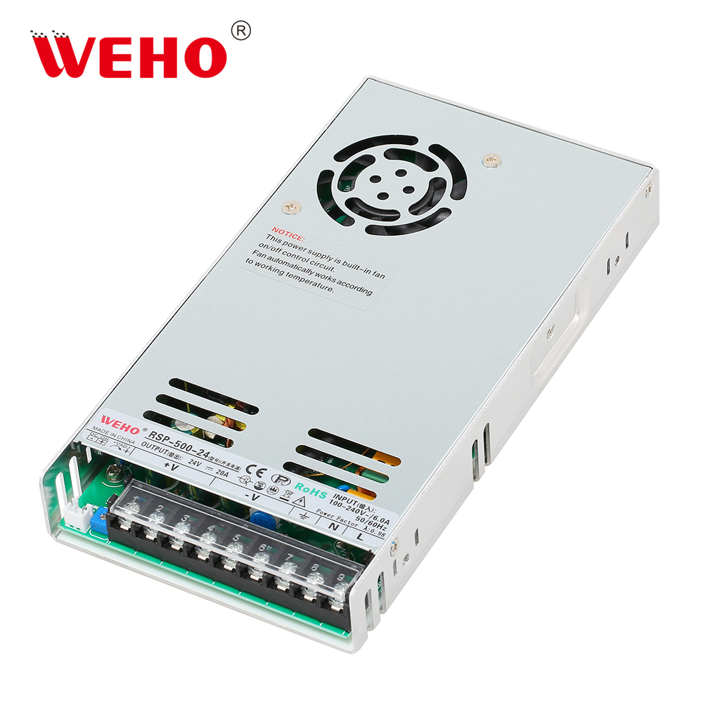
Ο WEHO RSP-500-24 product details identify a specific enclosed AC-DC candidate. The photograph shows its metal housing, fan opening and terminal area. Use the complete model and hardware revision to identify the unit covered by a requested surge report.
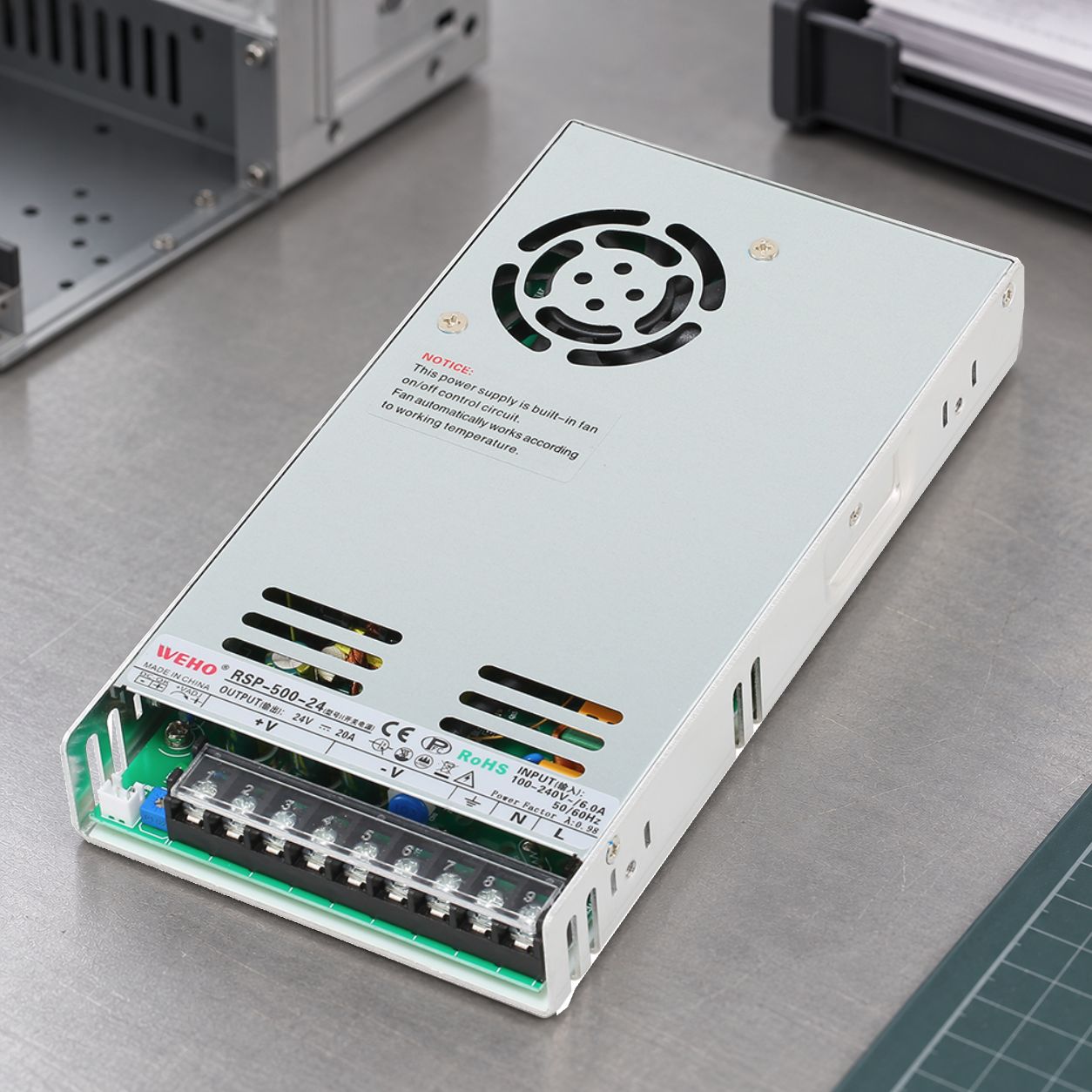
In the test-configuration record, distinguish the AC input conductors, protective-earth connection, DC output and the metal enclosure. Ask the report owner which port and coupling path were tested and how the housing was bonded in that setup. Retain terminal assignments, input and load conditions, cable arrangement and any external SPD with the report identifier.
The pictured fan opening describes the hardware under review; its appearance does not establish immunity or the fan’s behavior during a disturbance. Record the required operating state and actual functional observations from the test. No surge level or passed criterion is assigned to this RSP-500-24 photograph.
For the ordered revision, request the applicable report and the worksheet fields above. Keep any external protection and configuration restrictions in the candidate definition. A report for another RSP suffix, revision or manufacturer cannot supply this assembly’s result.
Reopen the affected conditions after a design change
A change from a short local connection to a longer external cable can reopen the port review. A revised enclosure bond, filter or SPD can reopen the configuration review. A new controller can change the functional acceptance criterion even when the same power supply remains fitted. Each change needs a reasoned assessment of the affected evidence rather than an automatic assertion that every previous test is invalid.
Use a simple disposition: accept the exact documented scope; request a missing report field; obtain an engineering equivalence assessment; or plan the additional system test. Name the owner and keep the decision with the drawing revision. This turns surge immunity from a catalogue adjective into a configuration that purchasing can preserve.
Send the laboratory a bounded question
Ask WEHO for exact-model surge evidence with the candidate revision, intended input, relevant ports, system diagram, external protection and required functional behavior. Request the report identifier and any configuration restrictions. The useful answer is a traceable test scope and an explicit gap list, followed by the project’s acceptance decision.
Questions during report review
Does a higher kV number always identify the better candidate?
Compare the full configuration and acceptance criterion first. Different ports, source impedances, external protection or allowed recovery behavior can make the numbers unsuitable for a direct ranking.
Does an IP67 enclosure prove surge immunity?
No. Enclosure ingress information and an electrical surge-immunity record address different questions. Retain the applicable evidence for each.