


- A controller’s front-panel protection claim does not automatically classify the complete cabinet.
- Verify the applicable cutout, panel surface, retention method and specified sealing parts as one assembly.
- Do not assign an IP rating to TX4-W from its appearance or another controller’s instructions.
- Release the installed boundary against documented conditions and appropriate assembly-level evidence.

Where a neat panel installation can leave an open question
A cabinet builder installs a controller in a painted door and sees an even front bezel. The project requires a defined environmental boundary, but the purchase record contains only a controller photograph. Before releasing the cabinet, identify which surfaces and openings the protection requirement covers and which assembly conditions the component documentation actually supports.
El TX4-W panel-controller reference identifies the relevant product form. The product illustration does not prove a particular gasket is supplied, establish an IP rating or qualify the assembled door. Obtain applicable-unit installation and environmental information before making those claims.
Define the protected boundary before choosing sealing details
An ingress-protection claim applies to an identified enclosure or protected part under defined conditions. The IEC 60529 publication description identifies the IP Code as a classification of protection provided by enclosures. It is not a visual rating assigned because a bezel fits closely against a panel.
Specify whether the project concerns the operator-facing side, the rear electronics, the complete closed cabinet or several boundaries with different exposures. Water reaching the front interface and condensation forming inside the enclosure are different mechanisms. A successful front-interface assessment cannot automatically resolve internal condensation or cable-entry performance.
Schneider Electric's IP Code explanation notes that equipment mounted on an enclosure can contribute to its protection and that different parts can have different protection levels. For an OEM, this makes the mounting interface part of the assembly specification. The component description and cabinet declaration must refer to compatible boundaries.
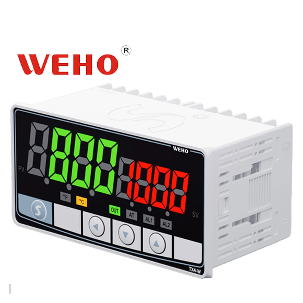
Treat “panel mount” as an installation description, not a waterproofing claim. The WEHO TX4 instructions provide installation context, but the material reviewed for this article does not establish a TX4-W assembly IP classification. Request the relevant environmental evidence for the exact supplied version if the project requires one.
Work a hypothetical assembly-release decision
Consider an OEM preparing a controller-door assembly for equipment exposed to a specified cleaning process. The project has an environmental requirement, but its exact protection claim and test method are controlled by the responsible equipment designer. No numeric IP class, panel thickness, cutout tolerance or fastening torque is invented in this example.
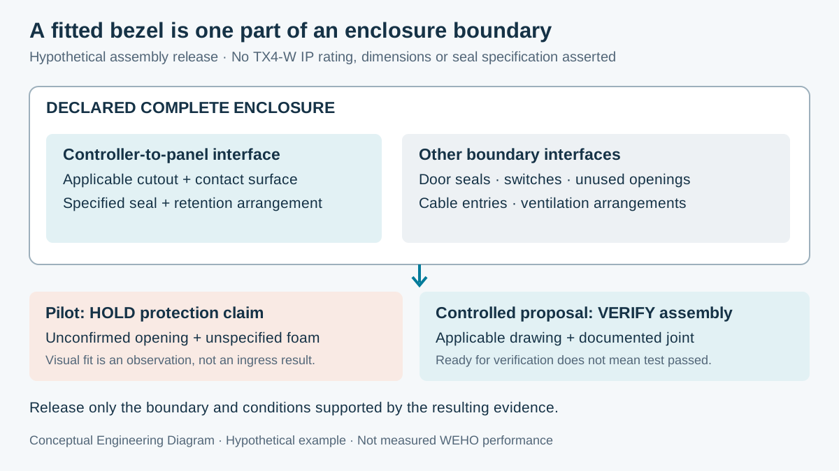
The first pilot panel uses an opening copied from a general outline drawing. Its edge has been refinished after painting, and the installer has added an unspecified foam strip. The assembly looks complete, but there is no controlled evidence tying that strip, the cutout and the retention arrangement to the required protection boundary.
The correct disposition is to hold the environmental release while retaining the verified mechanical observations. “Controller fits” can be recorded as an observation; “cabinet meets the required ingress classification” remains unsupported. The distinction preserves useful fabrication information without turning a visual check into a test result.
A second proposal uses the applicable controller mounting drawing, the manufacturer's specified sealing arrangement where one is required, and a controlled panel-finish process. The manufacturing record identifies the sealing-part revision and how its position is checked. This proposal is ready for the relevant assembly verification, but the document package alone is still not a completed ingress test.
The OEM must also inspect the rest of the declared boundary. Door seals, unused holes, switches, ventilation and cable entries can provide paths unrelated to the controller bezel. Passing a controller-interface check does not compensate for a separate unqualified opening elsewhere on the same enclosure.
Swipe horizontally on a small screen, or open the full-size diagram.
| Artículo | Pilot evidence | Required closure | Release disposition |
|---|---|---|---|
| Cutout and panel | Fits, but drawing revision is unconfirmed | Applicable opening, thickness and finish requirements | Hold protection claim |
| Sealing arrangement | Unspecified foam added locally | Documented compatible parts and installation method | Do not substitute by appearance |
| Retention | Bezel appears even | Required fixing method and assembly record | Visual fit alone is insufficient |
| Complete enclosure | Other entries not assessed | Boundary-wide verification under applicable conditions | Complete assembly acceptance remains open |
Make the assembly conditions traceable
A useful drawing package controls the physical interface as well as the controller outline. Identify the mounting-hole revision, allowed panel condition, sealing components and retention details. The WEHO mounting-drawing review covers the broader discipline of verifying controlled drawings before fabrication; the present task adds the protection boundary at an installed panel interface.
OMRON's E5CC installation instruction illustrates why controller sealing is assembly-specific: its documented waterproof mounting uses specified packing and excludes certain mounting arrangements. Those instructions apply to the named OMRON products. Their dimensions, torque and protection claims must not be copied into a TX4-W installation.
Check the panel surface that actually contacts the specified seal. Burrs, a distorted opening, coating ridges or damage can alter that contact even when the outer dimensions look familiar. Define the inspection and acceptance requirements from the applicable assembly documentation instead of prescribing an unsupported universal flatness or compression value.
Consider maintenance and replacement as part of the same controlled arrangement. A different gasket material, refinished door or replacement retention part may change the conditions behind an earlier qualification. The service record should identify changes that require reassessment, rather than assuming a once-qualified cabinet remains unchanged indefinitely.
Verify the interface and the complete enclosure
- Define the exposure. Record the project environment, the claimed boundary and the required protection evidence. Distinguish external ingress, internal condensation and chemical compatibility; a requirement for one does not automatically cover the others.
- Confirm the installation documents. Record the controller's complete identification and applicable mounting revision. Check whether the manufacturer specifies sealing parts, panel conditions or restrictions for the relevant claim; missing information remains a release item.
- Inspect the fabricated panel. Record opening identity, edge condition, contact surface and the documented panel requirements. Compare actual observations with the controlled drawing rather than accepting a bezel photograph as dimensional evidence.
- Record the assembly. Identify each specified seal or retention part and record its installed position and required fastening checks. Use the applicable procedure and acceptance criteria; additional force or improvised sealant is not a substitute for an unsupported joint.
- Verify the declared boundary. Have the responsible organization apply the appropriate assembly-level verification. Record configuration, method, conditions and results, then close other openings within the same boundary before releasing its environmental claim.
Do not introduce water into powered equipment as an informal cabinet check. Any verification involving hazardous energy or environmental exposure belongs in the responsible organization's controlled procedure with the necessary equipment isolation and protection. The article defines evidence to obtain rather than a field spray-test method.
When evidence supports only the front interface, state that limited scope in the release record. Keep the rear environment and cabinet boundary requirements visible to the equipment designer. Precise scope is more useful than a broad “waterproof” description that a buyer cannot reproduce or verify.
Request TX4-W installation evidence for the actual panel
Send the TX4-W mounting evidence enquiry with the ordered-unit identification, panel drawing, finish, intended exposure and required protection boundary. Ask for the applicable mounting and sealing information and any relevant restrictions. Include the assembly-release record so that the response addresses the actual interface rather than an unsupported cabinet-wide rating.
Engineering FAQ
Does a sealed-looking controller bezel prove the cabinet IP rating?
No, appearance does not prove an ingress-protection classification. The controller interface, other openings and declared enclosure boundary need appropriate evidence. A photograph cannot replace the relevant assembly conditions or verification result.
Can I copy another controller's gasket and tightening instructions?
No, installation instructions are specific to the product and arrangement they identify. Use the applicable controller documentation and compatible sealing components. Another manufacturer's example can explain the principle without supplying TX4 dimensions or torque values.
Does a front-panel protection claim cover the rear terminals?
Only include the rear terminals if the applicable claim explicitly covers them. Different parts can have different protection requirements and ratings. The cabinet design must provide the rear environment required by the installed controller.
Should a replacement gasket trigger a new review?
Review any replacement that changes the qualified sealing arrangement. Check part identity, material, condition and installation requirements against the controlled assembly. The responsible designer determines what verification the change requires before the environmental claim is retained.

