



An isolated DC-DC converter can still pass high-frequency common-mode current through capacitance. Galvanic separation interrupts a direct conductive connection; it does not eliminate the electric-field coupling between input and output. The equipment’s cables, shields, chassis, and test instruments complete the path that determines where that current flows.
For an OEM connecting isolated power to a sensor or communication interface, the practical question is whether the assembled system meets its noise and functional requirements. A withstand-voltage number alone cannot answer it. This article develops a current-path review and two hypothetical calculations; no WEHO model is assigned an isolation capacitance, noise performance, or safety insulation category.
Article sections
Trace a complete path across and around the barrier
Draw the primary-side return and the isolated-side return as distinct nodes. Then add the converter’s input-to-output capacitance, signal isolators, shield connections, enclosure capacitance, and any communication cable that reaches other grounded equipment. Include the mechanical arrangement because a metal mounting surface can change the effective capacitance.
Common-mode current is associated with the pair or group of conductors moving together relative to an external reference. Differential load current instead leaves on one supply conductor and returns on its partner. The distinction identifies which path to measure and why a good differential output-ripple result may coexist with a noisy cable interface.
RECOM’s EMC discussion explains the displacement-current relationship i = C × dV/dt. It also distinguishes short current impulses from the spectral or RMS quantities used for other evaluations. A sharp voltage transition can therefore matter even when the coupling capacitance looks small.
Read SD-50 isolation evidence separately from capacitance
El WEHO SD-50 DC-DC converter product page y SD-50 manufacturer specification illustrate the distinction. The PDF lists an input-to-output withstand-voltage item of 1.5 kV AC, but gives no input-to-output capacitance value. A withstand entry cannot supply the missing capacitance needed for the current-path calculation.
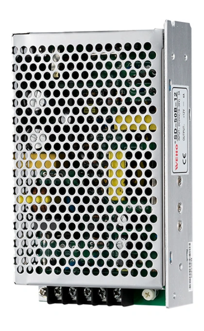
SD-50B-12 product photograph for document matching. Isolation capacitance and the applicable electrical ratings require evidence for the exact supplied assembly.
View original photograph ↗
Before reviewing an SD-50 assembly for an isolated interface, reconcile the complete model suffix, unit rating label, and applicable specification revision. The public product records and the pictured SD-50B-12 label are not fully aligned. Ask WEHO to confirm the input-voltage range, rated output voltage and current, and revision that apply to the offered unit before assigning electrical requirements. Request input-to-output capacitance with its measurement frequency, terminal grouping, and typical or maximum status, then evaluate the installed power-and-signal path.
El 20 pF and 100 pF values below remain hypothetical, with no value assigned to SD-50. Similarly, the document’s withstand entry does not establish a continuous working-voltage limit, safety insulation category, or the equipment’s common-mode noise result. The useful supplier deliverable is an exact assembly record plus the missing capacitance evidence, followed by a controlled connection test.
Calculate an edge-current screening example
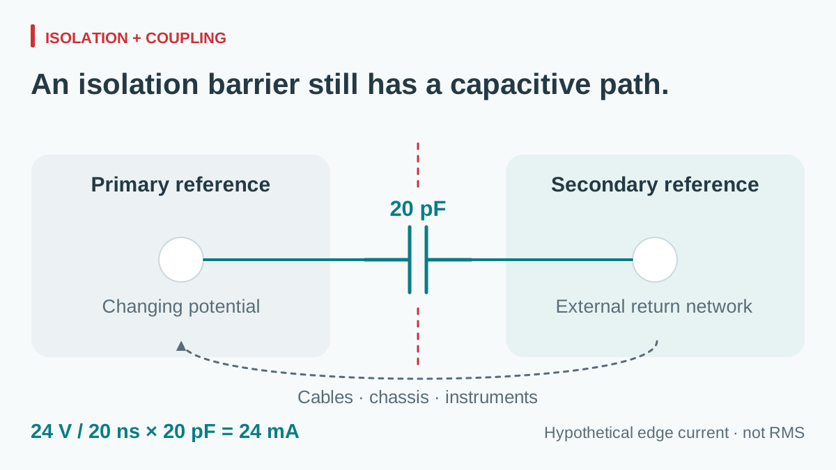
Assume a simplified coupling path with 20 pF effective capacitance and a voltage across that capacitance changing by 24 V in 20 ns. These are invented system inputs, not a converter specification. Approximate the edge as a linear ramp:
dV/dt = 24 V / 20 ns = 1.2 V/ns.
i = 20 pF × 1.2 V/ns = 24 mA during the ramp.
The associated charge movement per edge is Q = C × ΔV = 480 pC. If the effective path were instead 100 pF under the same imposed voltage ramp, the screening values would be 120 mA y 2.4 nC per edge. The ratio is five because the capacitance ratio is five.
| Hypothetical effective capacitance | Imposed edge | Ramp current | Charge per edge |
|---|---|---|---|
| 20 pF | 24 V in 20 ns | 24 mA | 480 pC |
| 100 pF | 24 V in 20 ns | 120 mA | 2.4 nC |
View full diagram ↗
These are lumped-circuit screening values. Actual voltage across the barrier can differ from the DC output rating, and the real network includes source impedance, inductance, distributed capacitance, and frequency-dependent return paths. Current does not become a real measured result simply because the equation is correct.
Do not compare the 24 mA ramp value directly with an RMS leakage limit or an RCD threshold. Duration, repetition, waveform, bandwidth, measurement network, and current division matter. Protective-conductor or touch-current assessment is a separate task with its applicable method; the calculation here does not establish safety compliance.
A sinusoidal component needs a different description
For a single sinusoidal voltage across an ideal capacitance, the RMS relationship is IRMS = 2πfCVRMS. At a hypothetical 500 kHz, 20 pF, and 1 V RMS across that capacitance, the current is approximately 62.8 µA RMS.
This is not another way to label the 24 V ramp above. It represents a different assumed waveform and voltage magnitude. A switching waveform contains multiple spectral components; each experiences the actual circuit impedance. Neither example predicts the common-mode voltage or communication error at a receiving device without the rest of that network.
Keep these quantities separate in the project worksheet: capacitance and its measurement conditions; voltage waveform across the boundary; current at a named conductor group; and the functional result at the receiver. This prevents a component-level comparison from quietly turning into a system guarantee.
Build a controlled connection test
Begin with the intended production arrangement and a stable equipment operating state. Record the converter identity, input and load, signal activity, cable lengths, shield terminations, enclosure, and instrument connections. Choose instruments with the bandwidth, isolation, and common-mode capability needed for that setup.
A current probe around both output conductors together can help examine their net external common-mode current because opposing load currents ideally cancel. It does not capture current in a separate shield or chassis lead that is outside the aperture. Probe imbalance, bandwidth, positioning, and other return paths remain part of the measurement uncertainty. Tektronix explains why current-probe sensitivity and waveform bandwidth need deliberate selection.
| Configuración | Question | Record together |
|---|---|---|
| Power and representative local load | What baseline path exists before external signals? | Pair current spectrum and output behavior |
| Required communication cable connected | Does the remote reference change the current path? | Cable/shield connections and receiver error counters |
| Production enclosure and mounting installed | Does the physical return network change? | Bonding locations, cable routes, and relevant spectral components |
| Input and load operating corners | Do switching states alter the interference? | Operating mode and repeatable functional metrics |
| Intended test instruments attached | Does the measuring setup change the result? | Probe return paths and any added capacitance |
Keep required protective bonding intact. A diagnostic comparison is not permission to disconnect PE or compromise an isolation barrier. Use manufacturer-permitted configurations and suitable isolated measurements; an ordinary grounded oscilloscope lead can create the very connection being investigated.
Review changes at the path they affect
Lower specified isolation capacitance can reduce one coupling path, but other paths may dominate. Compare values under the stated measurement frequency and terminal grouping, and determine whether a figure is typical or a guaranteed maximum. A value measured between one pair of terminals is not automatically the capacitance of the finished assembly. RECOM discusses isolation-capacitance measurement conditions in its datasheet-parameter guide.
A deliberate capacitor can redirect high-frequency current locally while increasing coupling across the isolation boundary. TDK-Lambda’s CC-E instructions show this tradeoff for specific products. Their component guidance belongs to those products and is not a generic capacitor recommendation for a WEHO converter or an assembled machine.
Any cross-barrier part needs review of its intended function, insulation requirements, permitted current, and effect on system performance. Similarly, a common-mode choke or a different shield termination acts on a particular path. Evaluate the changed assembly; do not infer success from the component name.
Preserve the distinction between this coupling problem and the choice of output voltage reference. A deliberate conductive bond can change the system’s galvanic boundary, whereas capacitance transfers time-varying displacement current. Both belong on the same path drawing, but they are different mechanisms.
Release a reproducible interface, not an isolation slogan
The qualification record should contain the path drawing, exact module and installation revision, capacitance data with conditions, named operating cases, instrument arrangement, receiver limits, and results before and after any change. Use a limit relevant to the equipment function and the applicable EMC method; a low cable-current reading alone does not prove immunity or compliance.
For the supply assembly itself, the broader OEM module qualification checklist keeps electrical interfaces, mounting, and controlled production evidence connected. It does not replace the isolation-path review.
Send WEHO your isolated power-and-signal interface requirements with the intended reference arrangement, operating voltages, load, cables, enclosure, and required evidence. Identify galvanic isolation as a requirement to verify for the exact candidate, then ask separately for available capacitance and EMC documentation. A common-mode test plan gives that discussion a measurable next step.




