For a constant-power LED driver, verify the documented voltage-current operating envelope at the selected current setting. The label can describe the ability to reach rated power across a range of settings; it is not enough to assume that the driver automatically forces the LED load to consume the same watts at every instant. Distinguish full-power capability, adjustable current and actual regulation before approving a luminaire design.
This is a different decision from selecting a constant-current driver solely by its voltage window. The additional question is which combinations of voltage and current can reach the required power, and what happens outside the full-power region.
On this page
Read the operating terms together
Manufacturer documents can distinguish adjustable output current, full-power current range, default current, output-voltage range and maximum output power. For example, Inventronics’ EUM-240SxxxDG product information presents those quantities separately. They should not be collapsed into one interchangeable “current range.”
Likewise, MEAN WELL’s XLG-150 specification uses constant-power terminology while also listing a constant-current region, current adjustment range and full-power current range. These are references for interpreting documentation, not evidence of the characteristics of a similarly named WEHO product.
Ask the supplier what the ordered variant actually regulates and how its setting is applied. A programmed constant-current operating point may deliver different output power as the LED forward voltage changes. An operating-envelope curve and a dynamic control law answer different questions.
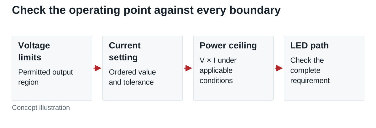
A power boundary is only one boundary
The arithmetic constraint is P = V × I. If a specified maximum output power is Pmax, a proposed combination must not exceed it. But satisfying that equation does not establish that the driver supports the voltage, current, dimming state or thermal condition involved.
Hypothetical envelope example: assume a fictional driver is documented for 24–48 V, adjustable current from 2–5 A, and no more than 120 W at the assumed thermal condition. Assume its permitted region includes the combinations below. These are teaching assumptions, not WEHO or other manufacturers’ product values.
| Selected current | Voltage needed for 120 W | Result under the assumed limits |
|---|---|---|
| 2 A | 120 ÷ 2 = 60 V | Outside the 48 V ceiling; at 48 V, output is only 96 W |
| 3 A | 120 ÷ 3 = 40 V | Full power is possible at 40 V if this point is otherwise permitted |
| 4 A | 120 ÷ 4 = 30 V | Full power is possible at 30 V if this point is otherwise permitted |
| 5 A | 120 ÷ 5 = 24 V | Full power occurs at the assumed lower voltage boundary |
The 2 A setting can be adjustable without being a full-power setting. At a 3 A setting, a load requiring more than 40 V cannot remain at 3 A within the assumed 120 W limit, even though 48 V appears elsewhere in the specification. The exact driver’s response outside its permitted region must come from its applicable documentation. Separate maximum values cannot be combined arbitrarily.
Place the LED load inside the region
Continue the hypothetical example with an LED assembly intended to operate at a regulated 3 A and with a documented forward-voltage requirement of 28–36 V across the project’s relevant conditions. Its output-power requirement is 3 × 28 = 84 W to 3 × 36 = 108 W.
Those points are below the assumed 120 W ceiling. The driver would not need to force 120 W into the LEDs for this requirement to be valid. Increasing current merely to reach the driver’s advertised watts would change the LED operating condition and could violate the LED assembly’s limits.
The arithmetic is only a screen. Confirm that the complete 28–36 V path is inside the selected current setting’s permitted region, including the documented temperature and input conditions. Include the allowed driver-current tolerance and the highest applicable LED forward-voltage condition, including cold start where relevant, when checking the power boundary. Then check startup, dimming and protection behavior separately. A power-envelope fit cannot substitute for those records.
Request an operating-point record, not a wattage promise
| Record | Evidence to obtain | Question it resolves |
|---|---|---|
| Exact variant | Model, suffix, firmware or programming option where relevant | Which operating map belongs to the order? |
| Current setting | Default, adjustment method, setting range and tolerance | What current will the LED assembly receive? |
| Full-power region | Applicable voltage-current plot and boundary conditions | Which settings can reach required output power? |
| LED requirement | Forward-voltage envelope and permitted current | Does the real load path fit? |
| Installation condition | Input, case/ambient limits, mounting and derating data | Does the published map apply here? |
| Dynamic behavior | Startup, dimming, open-load and recovery requirements | Does the luminaire operate acceptably between steady points? |
Freeze the programmed setting with the production identity. A purchasing description that names only the driver family can omit the parameter that determines LED current. Record who supplies the setting, how it is identified and what change requires requalification.
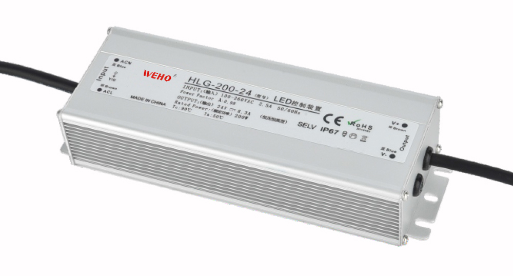
A useful rated-row example is WEHO HLG-200-24. The public HLG-200 specification lists 24 V and 8.3 A for this variant. That identifies a rated output point; the row alone does not establish a programmable current range or a full-power voltage-current region. Request the applicable operating map and current-setting evidence before treating the candidate as a constant-power solution. Match the delivered label and controlled specification to the exact order.

Separate a promising candidate from a released design
A candidate can proceed when its exact documents cover the required operating path and the relevant sample checks meet the project limits. Keep it on hold when the advertised mode, permitted map or ordered current remains unclear. If the load path leaves the region, evaluate a different driver or LED configuration instead of assuming the controller will compensate.
When evaluating a WEHO proposal, request the actual model’s mode and operating-region evidence. Do not transfer constant-power claims, settings or diagrams from another manufacturer or infer them from an XLG/HLG family name.
Share the LED operating envelope
Send the proposed driver identity, LED current, forward-voltage range, required dimming states, input and thermal conditions. Include the supplier’s operating map and programming requirement so the unanswered compatibility questions can be reviewed together.