



Key Engineering Takeaways
- The space between gear teeth still contains root metal; it is not automatically a no-target state.
- Qualify tooth width, root geometry, axial coverage and nearby metal using the actual target material.
- Calculate mechanical extremes separately from electrical switching thresholds.
- Establish distinct tooth and root states before investigating speed or receiving-system timing.
1. Define the metal geometry behind both logical states
A gear-detection task requires evidence that the sensor distinguishes a tooth from the intervening geometry. A visible slot between teeth does not prove that the inductive sensor sees an absent target: root metal, side plates and adjacent structure can remain nearby. A nominal distance to the tooth tip describes only one part of the target.
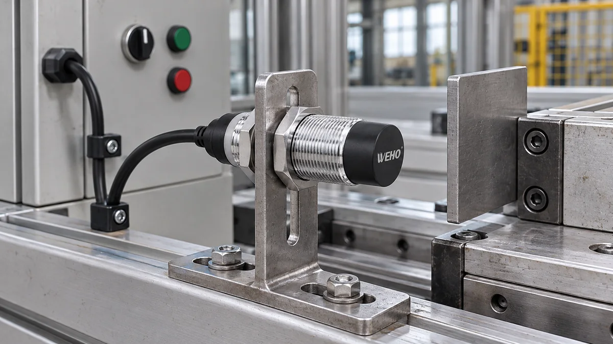
El WEHO LJA18 inductive proximity switch family is the ordinary product reference here. Its family picture does not establish a qualified gear sensor, an exact suffix or a switching threshold for the example dimensions. Request configuration-specific evidence and an actual-target evaluation before selecting a device for the task.
2. Understand what the reference target does and does not cover
A manufacturer's nominal sensing specification uses a defined reference target. OMRON describes that reference as having specified material, shape and dimensions. A gear tooth, narrow land or recessed root is a different target geometry, so matching only the nominal distance cannot establish equivalence to the reference test. OMRON proximity-sensor terminology
Target size and shape affect inductive detection. ifm notes that shape does not lend itself to a universal correction factor and recommends testing when the sensing distance is critical. Use that guidance to justify actual-target verification, without assigning ifm technology, correction factors or performance to a WEHO model. ifm inductive technology overview
The gear drawing should identify material, surface treatment, tip and root profiles, face width and the sensor's direction of approach. Include a section through the sensing position. A front photograph may hide a metal web or backing plate that remains behind a slot, while a simplified outline can omit the root fillet nearest the sensing face.
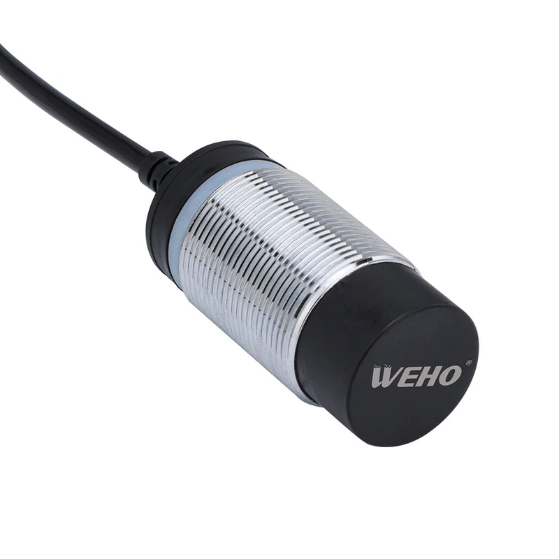
Evaluate the surrounding installation too. A metal bracket or nearby shaft feature can influence detection, and the relevant clearance depends on the actual sensor configuration. General proximity-sensor precautions identify surrounding metal as an influence; they do not provide a universal clearance for LJA18 family installations. OMRON proximity-sensor installation precautions
3. Calculate a hypothetical tooth-and-root envelope
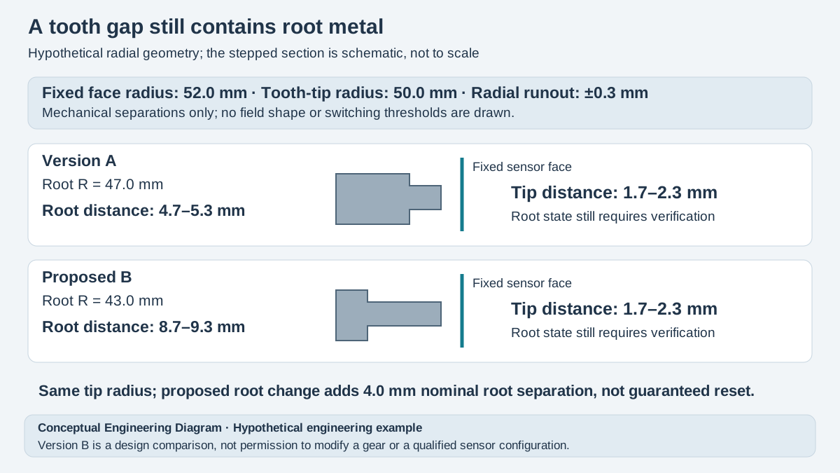
Consider an assumed radial arrangement with the sensor face at radius 52.0 mm from the shaft center. The gear has a 50.0 mm tooth-tip radius and a 47.0 mm root radius. Let radial runout at the sensing section be ±0.3 mm. Ignore mounting movement and other tolerances initially so the calculation remains transparent.
Nominal distance to the tooth tip is 52 − 50 = 2.0 mm. At the runout extremes, the distance ranges from 1.7 to 2.3 mm. Nominal distance to the root is 52 − 47 = 5.0 mm, ranging from 4.7 to 5.3 mm. These are mechanical separations, not predicted ON or OFF points.
| Hypothetical feature | Nominal geometry | Distance envelope | Unresolved detection question |
|---|---|---|---|
| Tooth tip | Radius 50.0 mm | 1.7–2.3 mm | Does the actual tooth produce the required state? |
| Root, version A | Radius 47.0 mm | 4.7–5.3 mm | Does retained root metal permit reset? |
| Root, proposed version B | Radius 43.0 mm | 8.7–9.3 mm | Does the changed target actually separate states? |
| Tooth / slot at defined drawing section | 4.0 / 4.0 mm nominal widths | Widths require their own tolerances | Are edge and center states distinct? |
Swipe horizontally on a small screen, or open the full-size diagram.
Version B illustrates a proposed geometric change, not a recommendation to machine an existing gear. Moving the root from radius 47 to 43 mm increases the nominal root separation by 4 mm while preserving the example tooth-tip radius. It does not prove reset, preserve mechanical strength or establish an acceptable gear design; mechanical approval remains a separate prerequisite.
The tip and root envelopes describe different angular positions over a revolution. Do not subtract their nearest extremes as though both occur simultaneously at one position. Actual runout, root fillets, axial offset and manufacturing variation should be evaluated at their corresponding positions and included in the final drawing-based qualification record.
The example supplies no LJA18 operating or release threshold. Without the actual sensor's documented conditions and target evaluation, neither 5 mm nor 9 mm can be called a guaranteed absent state. An attractive-looking geometric separation is only a candidate arrangement until the physical target and assembled installation have been checked.
4. Specify the physical samples and positions to evaluate
Begin with controlled stationary or otherwise safely indexed positions that isolate geometry. Check the tooth center, entering edge, slot center, root fillet and leaving edge where relevant to the application. The goal is to establish whether the target creates distinguishable states before changing speed, software filtering or pulse processing.
| Physical case | Record | Required observation | Decision boundary |
|---|---|---|---|
| Tooth center at geometry extremes | Actual material, width and face position | Required detected state | Only evaluated feature envelope covered |
| Root and slot center | Root profile, fillet and nearby metal | Required reset or alternative state | Visible slot alone is insufficient |
| Axial displacement extremes | Gear face coverage and sensor alignment | State separation retained | Drawing tolerances must match samples |
| Actual assembled bracket and background | Mounting revision and surrounding metal | No unintended persistent detection | Bench-only result cannot release assembly |
Preserve sample identity. A machined test coupon can help investigate a mechanism, but it may omit heat treatment, plating, tooth profile or backing metal present on the production part. Record every difference and decide which ones require an actual production sample. Do not silently promote a convenient coupon into evidence for the complete gear assembly.
A metal slot can differ from an isolated flag even when their leading edges look similar. The surrounding conductive material remains part of the sensing environment, and a family photo of ordinary flag detection therefore cannot demonstrate gear qualification. The technical model explains the geometry question; it does not depict a measured sensing field or an approved installation.
5. Qualify the geometry before evaluating dynamic performance
- Identify the target and sensor. Record gear drawing revision, alloy, treatment, complete sensor code and actual assembly information. Verify that the proposed sample and applicable supplier evidence match the intended components.
- Calculate corresponding geometric extremes. Record tip, root, fillet, axial position and mounting tolerances at the sensing section. Verify the arithmetic and identify omitted tolerances rather than treating a nominal tooth-tip distance as the full envelope.
- Index the relevant positions safely. Record the actual target positions, assembly state and observation method under the machine's authorized procedure. Verify the required tooth and root states without changing geometry and timing together.
- Resolve indistinct states mechanically and electrically. Record any supplier advice, alternative geometry or mounting revision. Verify each proposed change with the actual target and full surrounding metal before considering the geometric task closed.
- Release the geometry record conditionally. Record covered part variants and required rechecks after drawing or installation changes. Verify dynamic behavior separately once distinct physical states exist; geometry approval alone does not establish an operating speed.
If the root continues to produce the same state as the tooth, faster acquisition cannot create a physical contrast that the sensor has not demonstrated. Conversely, clear stationary states do not prove acceptable transitions during motion. Keep those two decisions linked but separate so a mechanical target problem is not hidden inside a timing adjustment.
A production change may preserve tooth count while changing detection geometry. Narrower teeth, a revised root fillet, a different alloy or an added metal guard should trigger a review of the approved record. Define those triggers during release, when the original evidence and supplier responses are still easy to retrieve.
6. Send WEHO a section drawing and qualification request
Send WEHO the complete LJA18 family inquiry and configuration information, gear section drawing, material specification and calculated geometric envelopes. Include the target-present and root-state observations, actual mounting arrangement and remaining evidence gaps. Do not send only a tooth count and nominal tip distance.
The next action is to confirm the actual sensor configuration, agree on representative physical cases and close the geometry record. Proceed to the separate dynamic evaluation only after the required tooth and intervening states have been established for the intended part and installation variations.
7. Frequently asked questions
Is the slot between gear teeth automatically a no-target state?
No, root metal, fillets, backing material or nearby structure can remain within the relevant sensing environment. Verify the required root or slot state with the actual target and installation rather than relying on its appearance.
Can a nominal tooth-tip distance prove that a gear will be detected?
No, the nominal distance omits target shape, material, width and installation variation. Calculate the geometric envelope and establish the required states using the actual sensor configuration and representative physical targets.
Does the example's deeper root guarantee sensor reset?
No, the deeper root changes a mechanical separation but does not establish an electrical reset threshold. Mechanical suitability and detection performance both require separate evidence before such a design change is approved.
Do distinct stationary states establish the maximum gear speed?
No, distinct stationary states establish only the evaluated geometric contrast. Dynamic switching and receiving-system behavior require a subsequent assessment under the intended motion and operating conditions.



