

Key Engineering Takeaways
- Check a fixed driver lead along its actual route, including termination and service movement, before cutting or ordering the harness.
- A straight-line gap between components is not the required cable length.
- Treat every length below as a hypothetical planning input, not a factory lead specification for HLG-150-24.
- Keep mechanical reach, electrical performance and sealed-joint qualification as separate acceptance decisions.
Why can a lead reach the box but fail at assembly?
A lead can touch a junction box and still be too short to terminate, support or maintain correctly. Luminaire OEMs need a repeatable harness definition before releasing cut lengths, otherwise a late connector change or mounting revision can consume the remaining cable.
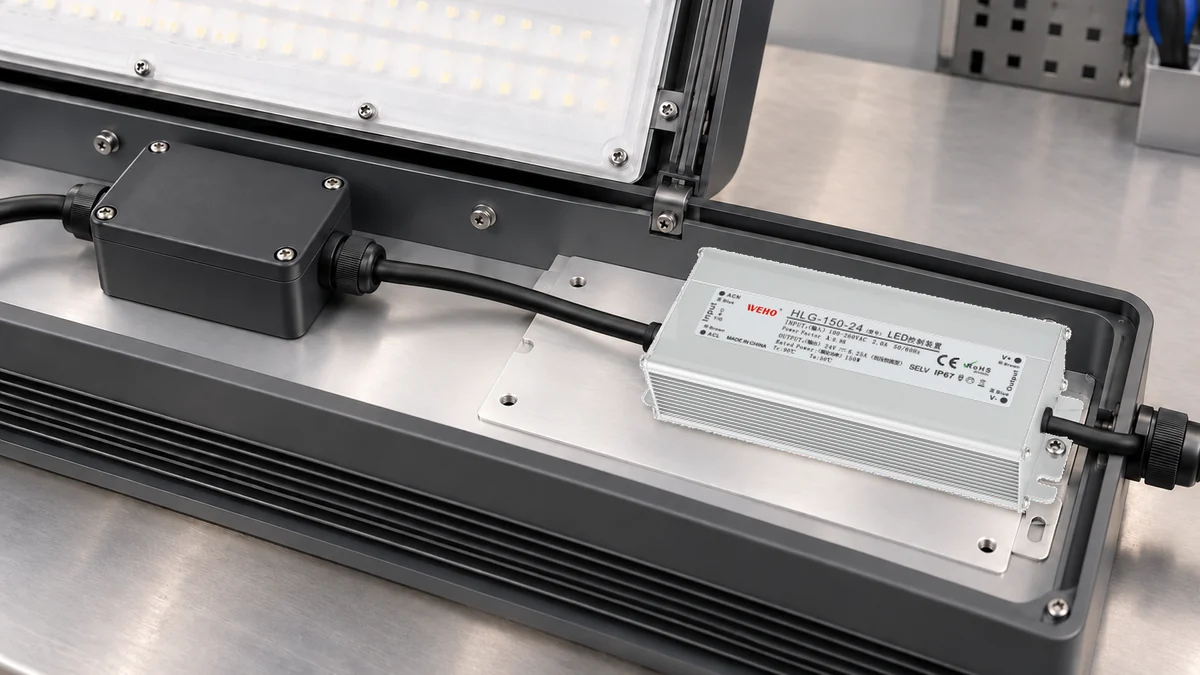
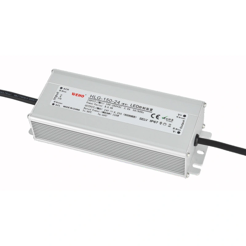
El HLG-150-24 fixed-lead product reference provides an identifiable driver for this planning method. Its two cable exits help locate the interfaces; the photograph does not establish a usable lead length or an approved cable route. Obtain the ordered revision’s cable information and check a representative supplied unit.
What should the harness drawing measure?
Measure the route between defined reference points, rather than choosing an overall number without explaining its endpoints. Identify where the fixed lead leaves the driver, where its outer jacket enters the connection system, and where each conductor must terminate. Keep jacket length and free-conductor length distinct.
A cable gland, connector or terminal enclosure may consume length differently. The required strip length, insertion depth, jacket grip and bending limits come from the selected components and assembly instructions. They are not values that can be inferred from the width of a driver label.
Define the installed driver position before measuring. A slotted mounting foot may allow several placements, but shifting the driver to rescue a short lead can change ventilation, mounting engagement or service access. Record the intended position and permitted variation, then verify the complete arrangement in that condition.
Use a physical route check when a drawing does not capture the cable’s natural approach. Follow the intended support points and obstacles, with the selected jacket, connector and gland. A loose string can help estimate a path, but it does not reproduce a cable’s bend behavior or prove that its strain management is acceptable.
How can an OEM separate the required allowances?
Separate route length from the additional length needed for assembly and service, and define each allowance so it is counted once. A drawing that merely adds a generous loop can hide an unresolved terminal-access problem or create a loop that obstructs a cover.
| Length element | Defined endpoints or purpose | Evidence to retain |
|---|---|---|
| Installed route | Driver cable exit to the specified connection reference, following the intended supports | Dimensioned route and representative assembly check |
| Termination allowance | Additional cable needed beyond that reference to complete the selected termination | Connector, gland and terminal instructions |
| Service movement | Additional length needed for a defined cover or tray movement | Demonstrated maintenance sequence and motion envelope |
| Assembly variation | Declared variation not already included in the preceding dimensions | Tolerance assumptions and measurement method |
The same path can be described with different datums. For example, one team may measure to the outside of a junction box while another measures to the terminal inside it. Without a controlled definition, both can add the entire internal distance and unintentionally count it twice.
Check both driver sides independently. A satisfactory AC-side route says nothing about the output-side route, and a longer purchased cable cannot be moved from one side to the other by relabeling it. Keep the physical cable-exit identity and the exact product’s wiring information consistent throughout the drawing and assembly record.
What does a complete lead-reach example look like?
A useful calculation states the assumed route, allowances and available usable length, then identifies what remains to be demonstrated. The following Hypothetical Harness Planning Example is arithmetic for a proposed assembly, not a WEHO cable-length specification or a measured installation.
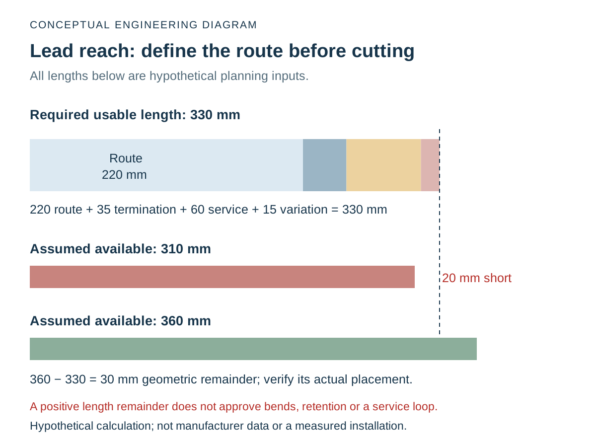
Assume a designer measures 220 mm along the planned route from a driver cable exit to a defined enclosure reference. The selected assembly requires another 35 mm for termination, a separately defined 60 mm for a service movement, and 15 mm for variation not included elsewhere.
| Artículo | Assumed value | Calculation or meaning | Decision |
|---|---|---|---|
| Installed route | 220 mm | Measured along the proposed supported path | Not the straight-line separation |
| Additional allowances | 35 + 60 + 15 mm | 110 mm, with nonoverlapping definitions | Instructions and motion check still required |
| Required usable length | 330 mm | 220 + 35 + 60 + 15 | Planning requirement for this example |
| Assumed available length | 310 mm | 310 − 330 = −20 mm | Does not meet the assumed route requirement |
| Revised available length | 360 mm | 360 − 330 = 30 mm | Geometric remainder only; verify its placement |
The second option leaves 30 mm against the assumed requirement, but that difference is not automatic service approval. The remaining length must occupy a location that preserves the applicable bend, support and protection requirements. A loop squeezed behind a terminal cover can fail even when the length arithmetic is positive.
A layout change can be preferable to a longer lead, but evaluate its complete consequences. Moving the connection enclosure may reduce route length while worsening tool access or exposure. Compare the revised assembly as a whole, rather than treating the cable shortfall as an isolated purchasing problem.
Swipe horizontally on a small screen, or open the full-size diagram.
How should the first assembly be checked before cutting a batch?
Check the representative complete assembly against the controlled harness definition, and retain measurements and observations that production can repeat. Verify the exact HLG-150-24 cable-exit identity rather than transferring another driver’s cable assumptions.
- Freeze the datums. Mark the driver position, connection reference and route on the current drawing. Record the drawing revision and the actual supplied configuration used for the check.
- Measure usable length. State whether the measurement includes stripped conductors, connectors or prepared ends. Compare that definition with the required route and allowances; retain any mismatch before modifying the sample.
- Demonstrate termination. Use the specified hardware and instructions to check insertion, jacket retention and access. Do not shorten a factory lead merely to match an unverified sketch.
- Check movement and closure. Under the equipment’s appropriate isolated maintenance procedure, demonstrate the intended service movement and cover closure. Record locations where the cable pulls, rubs or becomes trapped.
- Control the production release. Retain the accepted route, hardware and cut definition. Reopen the affected checks when a connector, enclosure, mounting position or service sequence changes.
A mechanical reach check does not establish voltage drop, startup performance or electromagnetic compatibility. If the proposal extends the power path, apply a separate LED-driver extension validation review using the actual electrical configuration. A factory-lead modification also needs the applicable supplier instructions and approval scope.
For sealed installations, the driver housing and the connection system have different boundaries. A cable reaching a box does not prove that the gland grips the selected jacket, that the joint meets the exposure requirement or that a service movement preserves the seal. Keep these acceptance records separate from the length worksheet.
What information should accompany a lead-length enquiry?
Send WEHO the proposed harness layout with the complete model, ordered revision, defined measurement endpoints, route, selected connection parts and required service movement. Ask which cable details or modification options are available for that configuration rather than assuming a custom lead can be supplied.
Include the expected quantity and production stage when those facts are known. An annotated assembly layout is more useful than a request for a longer wire without an endpoint definition. Retain the supplier’s response with the same controlled configuration before releasing purchasing or cutting instructions.
Engineering FAQ
Is the straight-line distance enough to specify the lead?
No. The required lead follows the actual supported route and includes separately defined termination, service and variation needs. Measure between controlled reference points and check the complete assembly rather than using a direct gap as the finished cable specification.
Does the example say HLG-150-24 has a 310 mm lead?
No. The 310 mm and 360 mm values are hypothetical comparison inputs, not HLG-150-24 specifications. Obtain the cable definition for the actual ordered revision and measure the supplied configuration using the same endpoints as the requirement.
Can a service loop replace strain relief?
No. A service loop provides geometric movement only; it does not establish acceptable cable retention or strain management. Follow the selected components’ instructions and demonstrate that the planned movement does not pull on the termination or compromise protection.
Does a successful reach check approve a cable extension?
No. Mechanical reach does not approve an extension’s electrical behavior or environmental protection. Check the actual circuit, conductor and connection requirements separately, and obtain the applicable supplier guidance before modifying the driver’s fixed leads.