For an SC-120-12 switching power supply review, budget the equipment load and battery-charging path separately. A lightly loaded main output does not establish extra charging current, and a charge-current figure cannot be added to the load-output rating. The purchasing decision needs two current budgets plus evidence of what happens while the battery reserve is restored.
This workflow is for an OEM reviewing a 12 V battery-backed assembly. Its deliverable is a channel-by-channel load sheet and a recovery acceptance record. Runtime selection and the choice between hold-up, a buffer and a DC UPS are separate decisions.
On this page
Start with the SC-120-12 variant
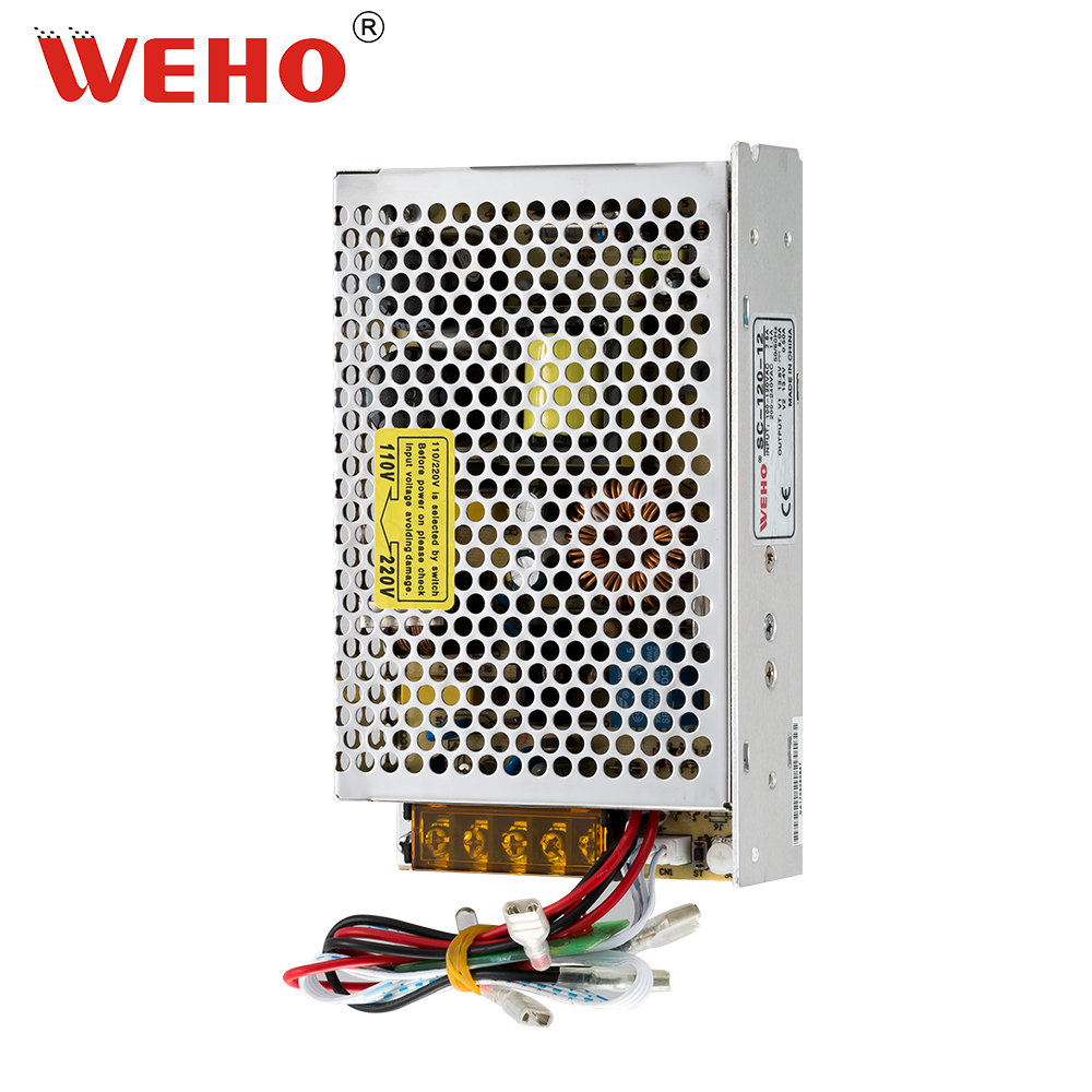
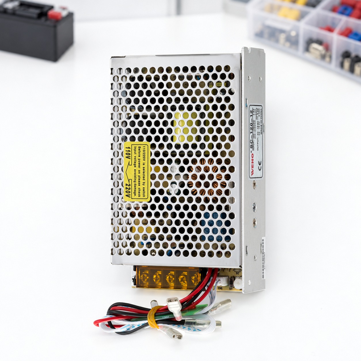
El published WEHO SC-120 specification lists SC-120-12 with CH1 at 13.8 V, 8.0 A and CH2 at 13.4 V, 0.50 A. Its 24 V variant has different values. Keep the full suffix on the load sheet and match it to the delivered unit and applicable document revision.
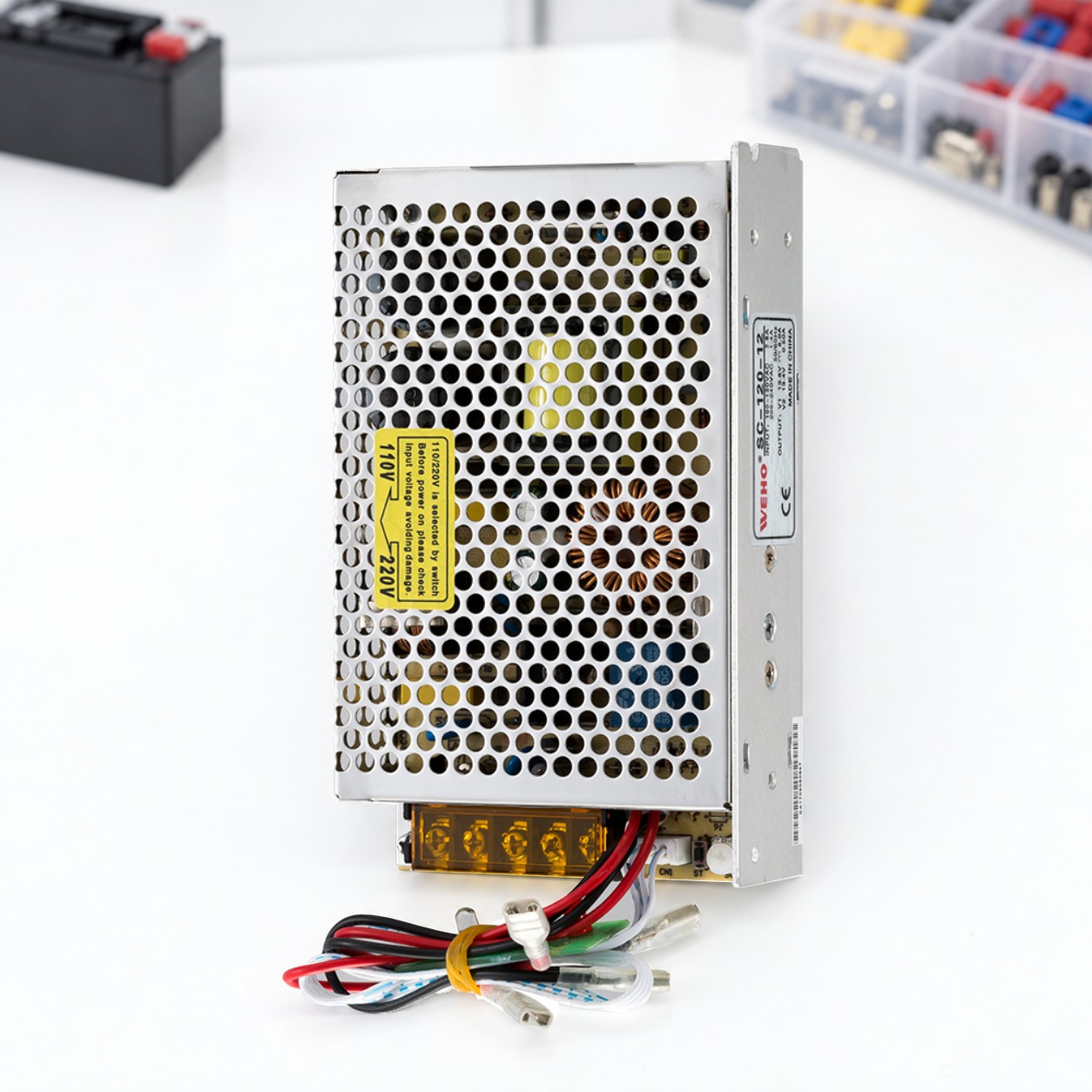
A nominal “12 V” device must accept the actual voltage presented in each operating state. Check the receiving equipment’s allowed range, cable drop and battery-mode behavior. The listed CH1 voltage does not prove that the output remains at 13.8 V throughout a battery discharge.
| Record | Listed value | Use in the review |
|---|---|---|
| El CH1 | 13.8 V; 8.0 A | Separate equipment-load budget |
| El CH2 | 13.4 V; 0.50 A | Separate charging-path inquiry |
| Potencia nominal | 117.1 W | Check channel allocation and operating conditions together |
| Input selection | 90–132 / 180–264 VAC, selected by switch | Match the input setting and applicable installation instructions |
Calculate two budgets at the same operating point
Hypothetical load schedule: electronics need 2.6 A, communications 2.1 A and auxiliary devices 1.3 A simultaneously. CH1 demand is therefore 6.0 A. At an assumed 13.8 V, that equals 82.8 W. If startup adds 1.2 A, the example reaches 7.2 A, or 99.36 W, during that defined event.
For a separate illustrative charging demand of 0.50 A at 13.4 V, charging power is 6.7 W. The arithmetic totals are 89.5 W during steady operation and 106.06 W during the example startup. These are calculated screening points, not measured SC-120 results or a product selection.
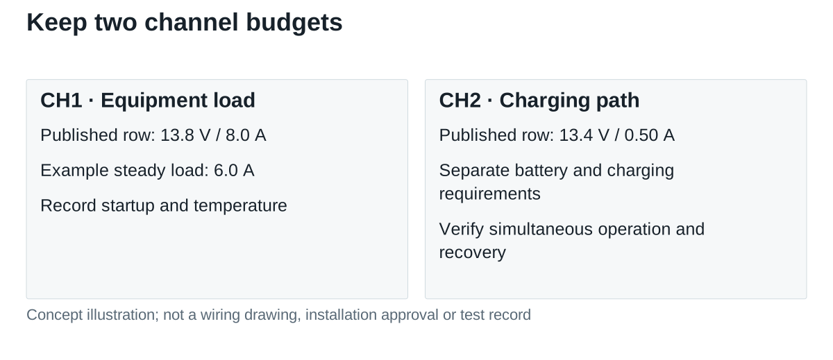
The sheet’s 117.1 W equals 13.8 × 8.0 + 13.4 × 0.50. That arithmetic reproduces the listed entries; it does not establish every permissible load/charge combination, transient or environmental condition. Ask which simultaneous conditions the current revision supports. Keep any unused CH1 capacity separate from the charging allocation.
The specification includes a derating curve. Compare the intended local temperature, input and installation with that curve rather than applying a full-power assumption across the working-temperature range. Record startup duration and repetition separately from continuous demand.
Turn a charging number into a recovery requirement
Specify the approved battery type, capacity, operating temperature and charging instructions before agreeing on recovery time. A voltage label alone does not establish battery-chemistry compatibility, an appropriate charging profile or a full-charge endpoint.
Illustrative arithmetic only: replacing a 0.25 Ah charge deficit at a constant 0.50 A would take 0.25 ÷ 0.50 = 0.50 hours. That simplified 30-minute result assumes constant current and no losses or taper. It is not a promised recharge time. Actual recovery needs the battery and charging-system data and a defined readiness criterion.
Ask for evidence with the equipment still operating during recovery. Define whether “ready” means a particular state of charge, a measured reserve sufficient for the next event, or another validated system criterion. An indicator alone needs a documented meaning before it can establish readiness.
Request a repeatable recovery record
| State to record | Required evidence |
|---|---|
| Normal supply and charging | CH1 load, charging current, both relevant voltages, input and local temperature |
| Input loss | Load-terminal voltage and required equipment function during takeover |
| Input return | Startup demand, load continuity, charging behavior and any alarms |
| Reserve restored | Defined readiness endpoint, elapsed time and response to the next required event |
Retain battery identity and condition, full supply suffix, wiring revision, settings and measurement points. Have the test owner state which limits passed and which remain open. This keeps a successful first backup event from being mistaken for verified repeat-event readiness.
Put these requirements in the purchase annex rather than relying on a generic UPS description. Ask the supplier to identify the document revision and the operating states covered by its response. When a battery, harness or load changes, compare the affected current and recovery records before carrying forward the earlier acceptance.
Review the WEHO SC-120 product details with the specification. Send WEHO the separate load and recovery requirements, including the battery proposal and required operating states, to request the matching model documents and remaining verification evidence.