



Select a relay from its documented DC switching capability for the actual load, then verify the complete assembly under the required duty. The supply’s available output current does not establish what the relay contacts can reliably interrupt.
For a panel buyer using a WEHO DR-15 supply, the deliverable is a relay qualification record covering contact voltage, load type, switching conditions and required life. Keep this contact decision separate from the relay coil’s own supply requirements.
Separate supply output, relay coil and relay contacts
را WEHO DR-15 product information and DR-15 specification sheet include a 24 V output option. That makes the family a relevant small DC-source example. It does not certify a relay, solenoid or complete load assembly.
There are three different questions: can the supply support the required load; can the control circuit operate the relay coil correctly; and can the contacts make, carry and break the load circuit under its actual conditions? A 24 V coil marking answers only part of the second question. It is not a 24 V DC contact-load approval.
Likewise, a prominently printed contact-current value may refer to a particular voltage and load category. Ask for the exact data table and switching-capacity curve instead of treating the number on the relay case as a complete specification.
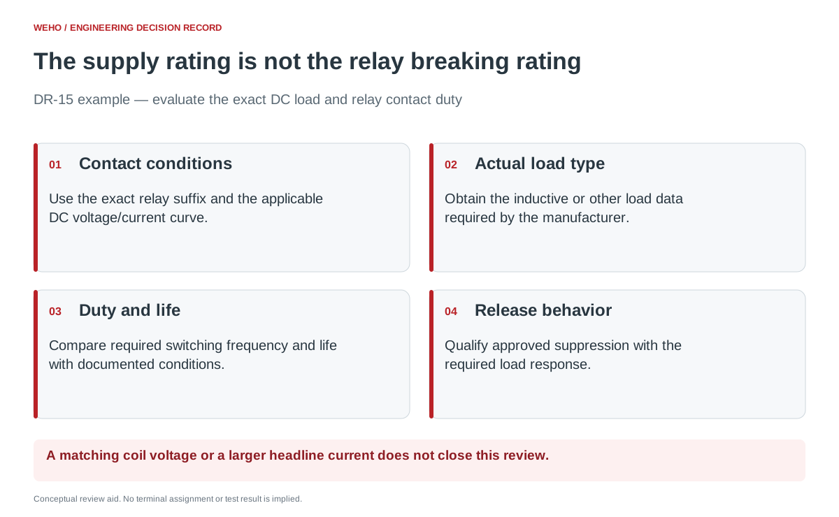
Describe the load that the contacts must interrupt
OMRON’s relay guidance explains that inductive-load switching capacity is generally lower than resistive-load capacity because of stored electromagnetic energy. Its published examples distinguish AC and DC load conditions. Those example ratings belong to the named OMRON products, not to an arbitrary relay connected to a DR-15.
Give the relay supplier the actual DC voltage range and current conditions at opening and closing. Identify whether the switched load is resistive, a coil, another inductive device or equipment with its own electronics. For an inductive load, obtain the load data needed to compare the relay’s stated time-constant or other specified conditions.
| Record field | Evidence to obtain | Decision it supports |
|---|---|---|
| Exact contact arrangement | Relay suffix, contact form, contact material where specified and manufacturer connection restrictions. | Ensures the curve applies to the offered device. |
| DC voltage and current | Applicable contact-load range and opening/closing conditions. | Places the real duty on the correct manufacturer curve. |
| Load characteristics | Resistive or inductive classification and required load data. | Avoids substituting a resistive rating for an inductive task. |
| Switching duty and life | Operating frequency, required cycles and endurance conditions. | Separates a maximum switching boundary from the required service life. |
| Suppression and release | Exact approved protection arrangement and required release behavior. | Checks both contact protection and the equipment’s response. |
If the load description is missing, record “selection evidence incomplete.” Do not reclassify an unknown load as resistive because its normal current is small.
Read the manufacturer curve as a combined condition
OMRON’s maximum-switching-capacity explanation evaluates contact voltage together with current on the appropriate AC/DC and load curve. This is why separate maximum-voltage and maximum-current fields cannot simply be combined into one assumed operating point.
For procurement, ask the relay supplier to identify the applicable curve and the proposed duty on it. Retain the curve revision and its conditions in the project file. If the published curve does not cover the load or endurance requirement, seek written application guidance or another relay rather than extrapolating an approval.
Check the meanings of any carry-current, maximum-switching-current and endurance entries separately. A contact that can conduct a stated current when closed is not thereby shown to break every load at that current. The acceptable operating point and expected life must come from the applicable documentation and validation.
Treat suppression as part of the qualified configuration
OMRON’s contact-protection guidance describes different suppression approaches and notes that protection can alter release time. For a DC inductive load, that means contact-protection performance and load-release behavior need to be considered together.
Do not add an unspecified diode or other suppressor and assume the whole decision is resolved. Use the design approved for the exact load and switching device. Record the component identity, manufacturer instructions and the required timing behavior in the assembly’s qualification package.
The relay coil and the switched load can also be separate inductive elements. Identify which one a protection claim concerns. A feature built into the relay’s coil circuit does not automatically protect the separate load switched by its contacts.
A hypothetical valve review shows why spare watts are insufficient
Consider a small panel whose DR-15 output option has already been checked against its steady load. A supplier proposes a relay because its headline contact-current rating is larger than that load. The controlled device is a DC solenoid, but the quotation includes only an AC resistive rating.
The review remains open. Request the proposed relay’s DC inductive switching data, applicable load conditions, required life and approved suppression configuration. More unused supply capacity would not supply that missing evidence. A larger source may change available fault energy, but it does not grant a relay a new breaking rating.
This example describes a document decision, not a tested DR-15/valve combination. Once a candidate is supported by the data, the responsible engineering team should verify actual load operation, release behavior and the required endurance basis using an approved test plan.
Release the exact relay-and-load combination
Close the record with the selected relay suffix, contact-load evidence, suppression version, required duty and validation disposition. Preserve open items that affect interruption or release behavior; do not hide them under a general “power supply checked” approval.
Keep substitutions under the same review. A replacement relay with the same coil voltage, footprint and headline current may have different DC load curves or endurance conditions. Purchasing can prevent an unsupported substitution by including those conditions in the approved-part record.
Use the project record
Open the blank DC Load Relay — Switching Qualification Record to record your conditions, evidence and decisions. The worksheet contains no pre-approved result.
Review the DR-15 source requirements alongside the load record
Send WEHO the requested DR-15 output version, complete load list, operating duty and any startup or transient conditions. Use the relay manufacturer’s exact contact data to qualify switching; request WEHO’s applicable supply documents for the source side of that review.




