For an LRS-350-36 assembly, make the AC input-selector state a controlled production and handover item. The power source configuration must match the installation’s AC supply before energization. A correct output-voltage suffix does not establish that the input selector is in the required position.
On this page
This guide addresses assembly control for an OEM or panel shop: how to prevent an unverified selector state from passing through inspection, packing and installation. It does not treat a manual input-range selector as an automatic universal-input function.
Identify the exact model and the documented input arrangement
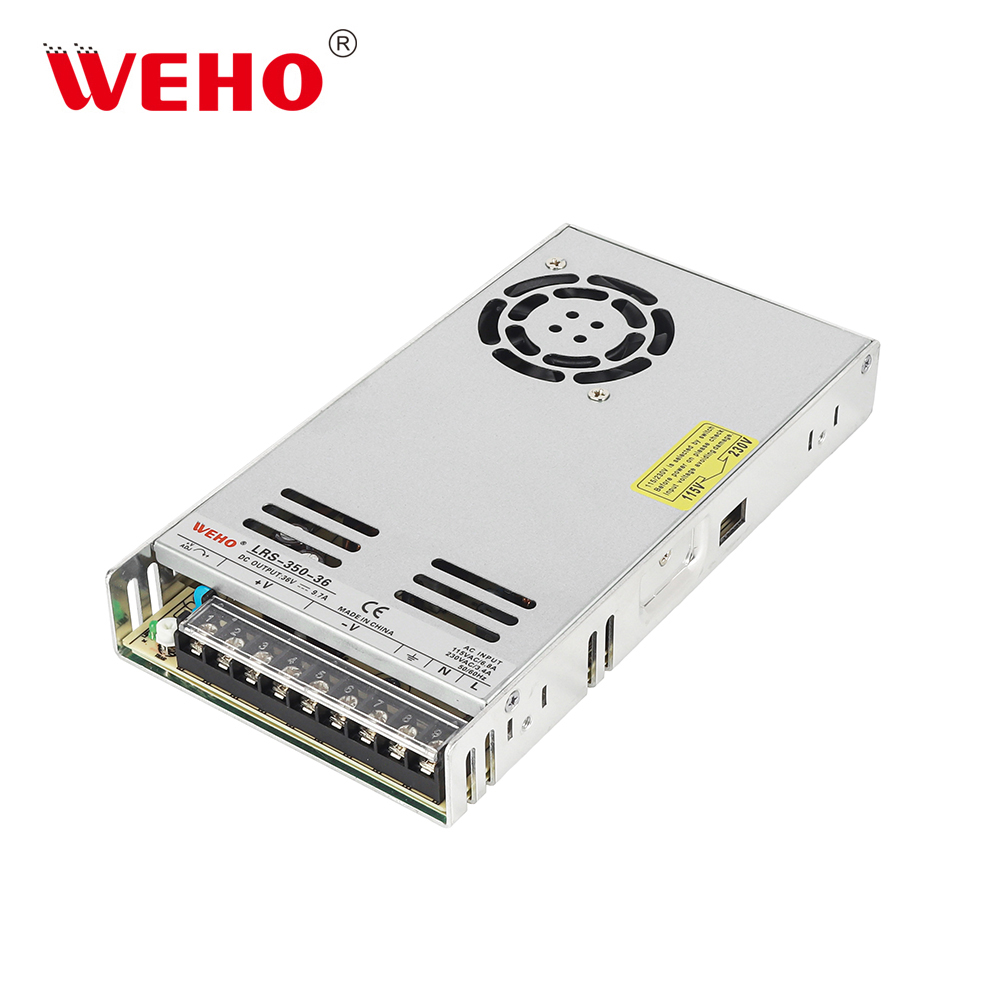
را WEHO LRS-350-36 is the exact pictured product reference. Its visible 115 V/230 V input-selector markings identify a manual configuration item. They do not establish an automatically selected, continuous universal AC input range.
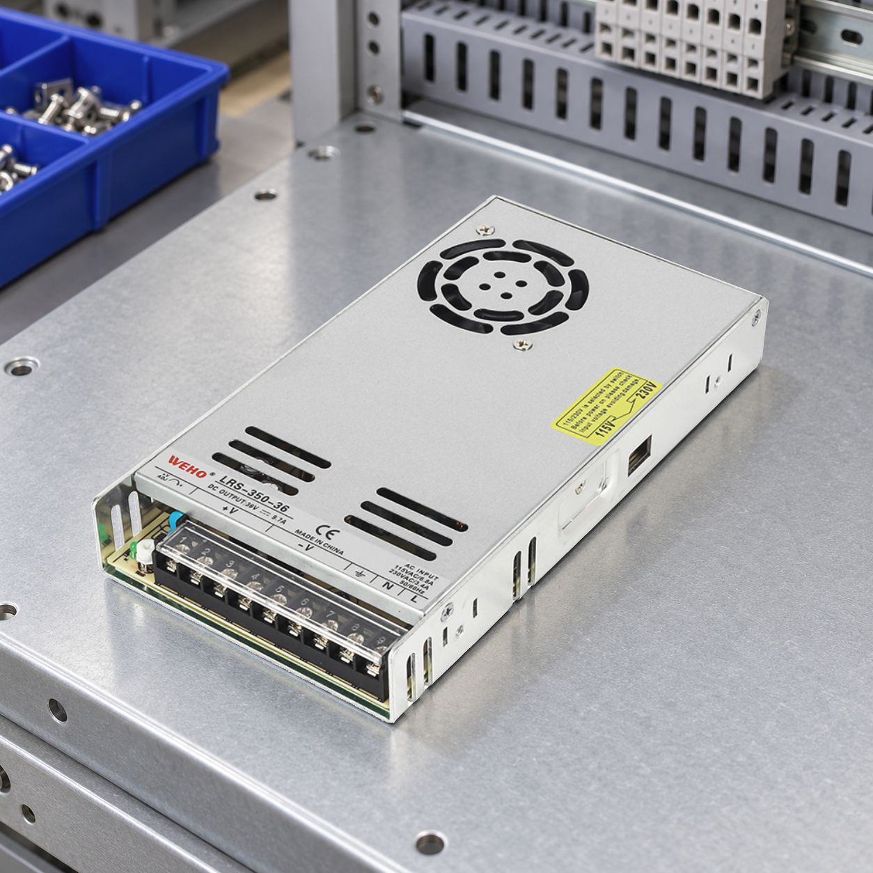
Use the supplied unit’s markings and applicable instructions to establish the permitted AC band for each selector state. The public LRS-350 sheet illustrates a manually selected input arrangement, but its output table does not identify the pictured 36 V variant. Do not transfer that table’s ratings or detailed input limits to this exact assembly without confirmation.
Keep a clear identity photograph of the actual unit or approved sample with the assembly instruction. Obtain the source-specific instructions before writing the test conditions. Do not infer a universal left/right or up/down setting from a different model’s switch.
Create a configuration row before releasing the work order
Assign each equipment variant an intended AC band, the corresponding documented selector state and the person or station responsible for verification. Keep this separate from the DC output requirement. A BOM field stating the DC output voltage cannot substitute for an input configuration field.
Hypothetical work-order example: ten otherwise similar cabinets include six destined for a nominal 115 V installation and four for a nominal 230 V installation. The source terminal voltage must fall within the band confirmed for that exact supplied revision. Record a selector check for all ten cabinets; an order-level note that says “export version” cannot identify which six receive which configuration.
| Example equipment group | Supply condition to confirm | Controlled assembly evidence |
|---|---|---|
| Six 115 V-market cabinets | Actual AC range fits the confirmed band associated with the 115 V selector marking | Correct band/state association for the exact unit; individual verification record |
| Four 230 V-market cabinets | Actual AC range fits the confirmed band associated with the 230 V selector marking | Correct band/state association for the exact unit; individual verification record |
The quantities are illustrative. The control principle is that every assembled unit has an attributable configuration, even if all ten use the same output-voltage model. Destination alone is insufficient where a site has several distribution voltages.
Verify the state before power is applied
The approved work instruction should identify the de-energized and isolated condition required for examining or changing the selector. Verify isolation using the equipment’s established procedure and account for other connected energy sources. Make this a defined checkpoint before the initial powered test, rather than trying settings to discover which one produces an output.
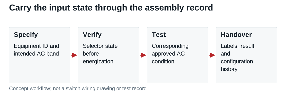
For the powered acceptance step, the authorized fixture must apply the AC condition corresponding to the released configuration. A test log with only DC output voltage leaves the input state untraceable. Record the unit identity, intended band, verified selector state, applied input condition and observed result together.
Changing the destination after test reopens the configuration check. If a unit is reconfigured, follow the applicable instructions and repeat the affected acceptance steps. A previous pass on one input arrangement does not document a later switch state.
Carry the identity through packing and installation
Make the equipment’s installation information consistent with the tested state. Use the controlled equipment labeling and dispatch record required for that assembly; do not alter or cover the supply’s original safety markings. The installer should be able to match the equipment ID, its permitted AC conditions and its released source configuration.
Where the finished enclosure makes the selector difficult to inspect, retain the assembly-stage evidence before closing it. That record supports traceability; it does not authorize energizing equipment whose actual present configuration is uncertain. The commissioning procedure must still establish the installation’s supply conditions and configuration.
| Handover field | Content to retain |
|---|---|
| Source identity | LRS-350-36 exact supplied assembly/revision and associated specification |
| پیکربندی | Intended AC band and verified selector state |
| Acceptance | Applied AC condition, result, equipment ID and responsible station |
| Dispatch/service | Consistent equipment label, installation information and reconfiguration rule |
Keep input configuration separate from protection approval
The selector record proves which input arrangement was verified. It does not establish suitability of a downstream load, protection coordination or every installation condition. Those remain separate engineering checks against the identified source and equipment configuration.
Send WEHO your proposed AC bands and equipment variant schedule when requesting the LRS-350-36 installation information. Ask for the instructions applicable to the supplied revision, then attach the resulting state-verification rule to assembly and service documentation.