



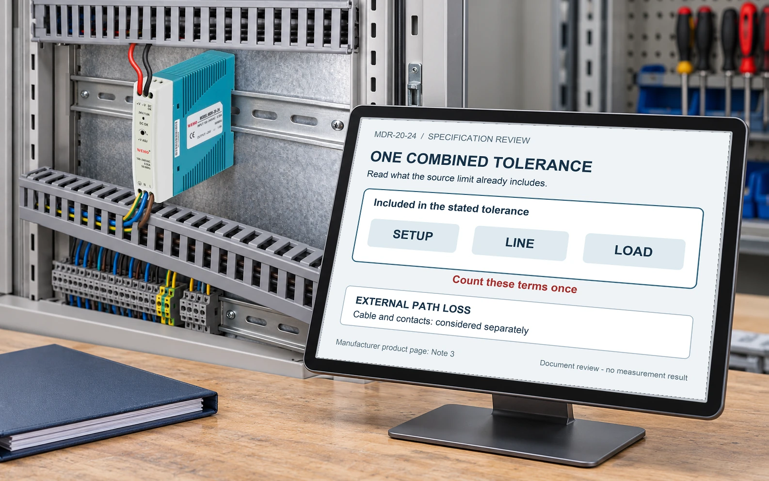
When a datasheet says voltage tolerance already includes setup tolerance, line regulation and load regulation, do not add those same terms again without a separate reason. Read the note that defines the number before building a worst-case receiver voltage budget.
The MDR-20-24 provides a useful documented example. This article is for an OEM reviewer comparing a receiver’s allowable input with a source specification; it does not convert typical performance into a guaranteed system limit.
Read the tolerance note with the model column
را MDR-20 product table gives ±1.0% voltage tolerance for the 24 V column. Note 3 states that tolerance includes setup tolerance, line regulation and load regulation. The separate ±1.0% line and load rows should therefore not automatically be summed on top of the stated combined tolerance.
Keep the exact model, revision and conditions attached to that interpretation. Note 1 states the default measurement conditions for unspecified parameters. A note that defines included terms does not erase separate environmental, wiring or transient conditions that the receiver must also survive.
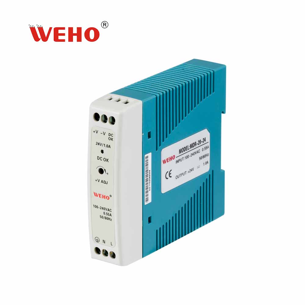
Calculate the stated DC tolerance envelope first
At an assumed nominal setting of 24.00 V, ±1.0% is ±0.24 V. The corresponding preliminary DC envelope is 23.76–24.24 V. Automatically adding another one percent for line and another for load would produce 23.28–24.72 V and count included terms more than once.
This arithmetic does not prove that every unit in every enclosure remains within the first envelope. Check the table’s conditions, the actual approved setting and any separate applicable temperature or installation effects. If a supplier defines a different combined limit for the supplied revision, use that documented definition.
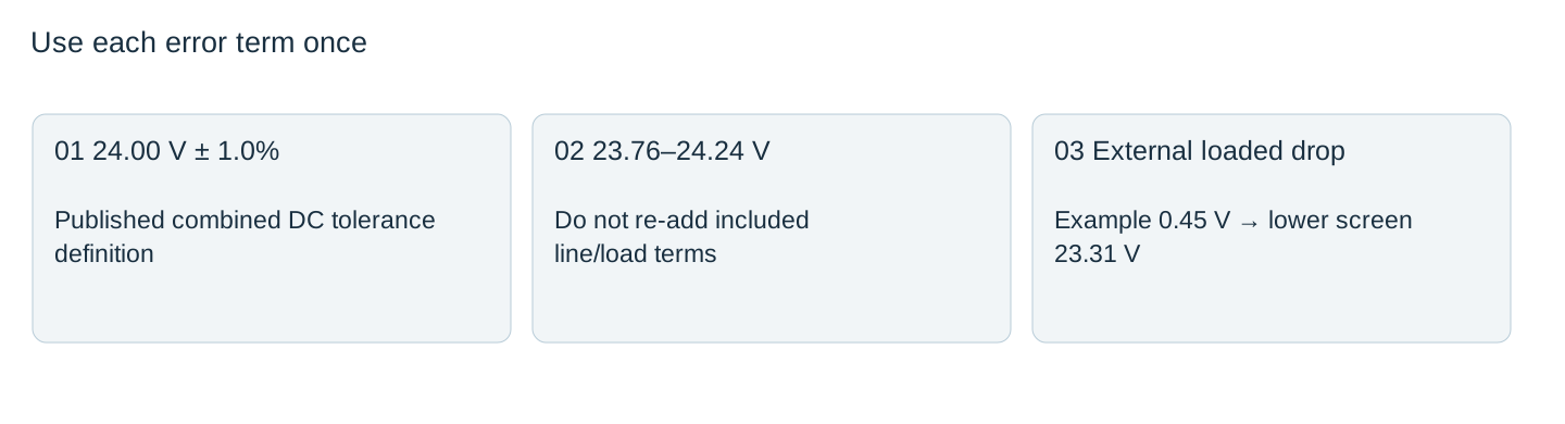

Keep cable loss, ripple and events in their own categories
| مورد | Treatment in a budget | Important distinction |
|---|---|---|
| Combined DC tolerance | Use its documented included terms | Do not re-add the same line/load errors |
| Cable and contact drop | Subtract the applicable loaded path loss | It occurs outside the source measurement points |
| موج و نویز | Use the stated method, bandwidth and receiver criterion | Peak-to-peak ripple is not a DC accuracy percentage |
| Transient response | Check time-dependent receiver limits | A steady-state tolerance is not a transient bound |
| Temperature effect | Apply only the applicable documented relationship | Do not invent the reference or direction |
The table lists 150 mV peak-to-peak ripple and noise for the 24 V column, with a stated measurement method. That is not permission to add 150 mV to both ends of a DC tolerance range. Whether and how a dynamic waveform is combined depends on the source definition and the receiver’s actual acceptance criterion.
Apply an external path loss to the correct envelope
Suppose a hypothetical approved DC source envelope is 23.76–24.24 V and the external path can lose up to 0.45 V under load. A preliminary loaded lower value is 23.31 V. The upper value needs its own state analysis: with negligible load the path drop may be near zero, so subtracting 0.45 V from the upper source value would incorrectly hide a possible 24.24 V receiver condition.
Use the receiver’s documented minimum and maximum for the relevant steady and dynamic conditions. If its minimum is 23.5 V, this illustrative lower-value screen fails by 0.19 V. Do not round away that result or increase the source setting without reopening the upper-voltage and other-load checks.
Make the budget reproducible for purchasing and service
For each term, record where it is measured, whether it is already included elsewhere, its sign and conditions, and its source. Keep unknown terms visible in the engineering record. This prevents both excessive pessimism from double counting and false optimism from silently dropping a real loss.
At acceptance, measure using a method appropriate to the particular criterion. A handheld DC reading, a bandwidth-limited noise measurement and a transient capture answer different questions. Compare each with its corresponding limit and preserve the instrument settings and circuit state.
For an MDR-20-24 voltage-budget review, send the exact datasheet revision, approved setpoint, receiver limits and a worksheet identifying included tolerance terms, external drops and dynamic criteria. Ask for clarification of any undocumented term before converting the budget into an acceptance limit.
Voltage budget term register
| Term | Included in another term? | Limit and direction | Source/conditions | Budget result |
|---|---|---|---|---|
Blank project worksheet. Enter verified project data; example calculations above are not measurements.



