



Key Engineering Takeaways
- Series or parallel sensor wiring requires permission for the exact output circuit and connected load.
- A correct AND/OR truth table does not establish electrical compatibility.
- Include simultaneous operation, loss of one sensor supply and the receiver’s OFF state in verification.
- Separate PLC inputs preserve individual sensor information and allow the required logic to be implemented explicitly.

Start with the decision the machine must make
Combining two inductive sensor signals can reduce input count, but it also changes fault visibility. Two separate part-present signals become one combined indication. An unexpected output pulse, an unpowered sensor or a leakage path can then affect the shared receiver. Define the machine's required response before choosing a wiring arrangement.
را WEHO LJA18 inductive sensor product page distinguishes several output variants. Record the complete ordered suffix and its corresponding connection instructions. A family photograph identifies the product range; it does not establish the output circuit inside a received sensor or permission to connect that output to another one.

For one sensor connected to one input, the existing proximity sensor and PLC integration article covers the basic interface. The additional task here is to approve the behavior of several sensors acting on one logical result, including conditions that ordinary target detection does not reveal.
Separate the truth table from the electrical circuit
AND and OR describe logical relationships. For positive detection logic, AND is true when both required conditions are present; OR is true when either condition is present. A normally closed output changes the relationship between the physical target and the electrical input, so write down which state each variable represents.
This hypothetical process example uses two independent target-present variables, A and B. The required indication is “at least one lane contains a component.” The table defines the intended software result before any output wires are connected.
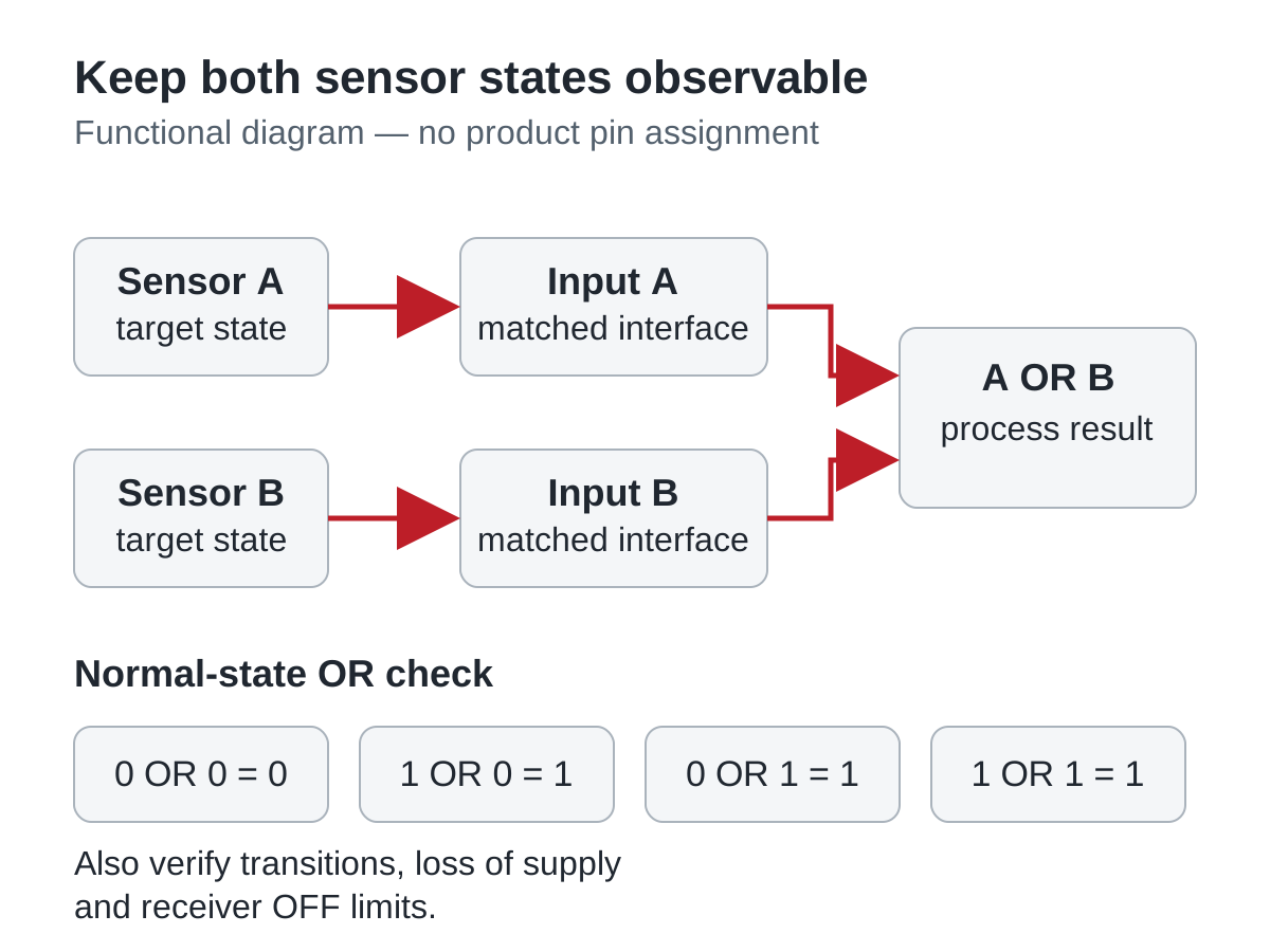
Swipe horizontally on a small screen, or open the full-size diagram.
| Target A | Target B | Required OR | Required AND | Record to retain |
|---|---|---|---|---|
| Absent: 0 | Absent: 0 | 0 | 0 | Receiver returns to its defined OFF state |
| Present: 1 | Absent: 0 | 1 | 0 | A acts without depending on B |
| Absent: 0 | Present: 1 | 1 | 0 | B acts without depending on A |
| Present: 1 | Present: 1 | 1 | 1 | Simultaneous operation and subsequent release |
A result that works in these four normal states can still fail during transitions. Include A releasing while B remains active and the reverse order. Record whether the receiver briefly changes state, how long that change lasts and whether downstream filtering or program execution accepts it. Define the allowed behavior from the process requirement, rather than hiding an unexplained pulse with an arbitrary delay.
Why output type and model authorization come first
An output transistor is an electronic interface, not an isolated relay contact. Its behavior when active, inactive and unpowered depends on its circuit. An NPN or PNP label alone does not specify reverse-current tolerance, interaction with another output or the operating conditions of a cascaded sensor.
OMRON's series/parallel connection FAQ treats DC two-wire, AC two-wire and DC three-wire arrangements separately. Some stated cases require relay interfaces, and the FAQ identifies possible startup pulses and reset problems. Those product-specific examples demonstrate why a universal connection rule is unsuitable; their permitted sensor counts are not specifications for WEHO products.
For a proposed hardwired arrangement, obtain the exact sensor instructions and receiver data together. Request the permitted topology, number of devices, load range, residual voltage, leakage current and power-sequencing behavior. Where the documentation does not authorize the intended combination, retain separate inputs or seek a documented interface solution before release.
Use a bounded electrical example to reject an unsuitable proposal
A voltage budget can reject a proposed series arrangement even when its logical AND behavior looks correct. The following numbers are hypothetical and apply only to an assumed, manufacturer-authorized topology. They are not LJA18 ratings or instructions to connect sensors in series.
Assume the available supply minimum is 21.6 V, three series devices each have a maximum 1.5 V residual drop under the relevant load, and the receiver requires at least 18.0 V to guarantee ON. First calculate the device drops:
Total residual drop = 3 × 1.5 V = 4.5 V.
Available receiver voltage = 21.6 V − 4.5 V = 17.1 V.
The proposal misses the assumed ON requirement by 0.9 V, even before cable and contact losses are included. Reject that electrical budget. Increasing the nominal supply is not an automatic remedy: every connected device's permitted voltage and the complete operating range would need another review.
For a parallel arrangement, make a separate OFF-state budget using documented leakage paths and the receiver's guaranteed OFF limits. Do not assume that one successful ON measurement also proves reliable release. Added interfaces, indicator circuits and unpowered devices may introduce paths that a simple sum of sensor leakage does not represent.
Compare shared wiring with separate PLC inputs
Separate inputs provide distinct observations of A and B. Software can calculate OR for the process while retaining the individual states for diagnostics. That architecture still needs compatible sensor/input circuits, correct references and suitable timing. It does not turn ordinary sensors or a standard PLC into a safety system.
| Review point | Shared AND/OR wiring | Separate PLC inputs | Decision evidence |
|---|---|---|---|
| Electrical permission | Exact combination must be authorized | Each sensor/input interface must match | Model instructions and receiver specification |
| Simultaneous targets | Possible interaction at the shared node | Two individually observable states | Both-active and release-order records |
| One sensor loses supply | May affect the combined signal | May appear as a normal state unless diagnostics exist | Defined power-loss response |
| Fault localization | Combined indication can conceal the source | Individual states support diagnosis | Service requirements and fault table |
The process owner should decide whether losing individual information is acceptable. For example, a combined OR cannot distinguish “A present” from “B present” at its single receiver. If maintenance needs that distinction, saving one input may create an avoidable troubleshooting burden. Document that tradeoff as part of the machine specification.
Verify normal states, transitions and loss of power
Use a controlled commissioning plan with machine motion or hazardous process energy prevented as required by the equipment design. Verification should observe the electrical receiver and the resulting program state together. A sensor indicator alone cannot show what a PLC sampled.
- Identify the components. Record complete sensor suffixes, receiver channel type, supply arrangement and instruction revisions. Verify that each received component matches the reviewed interface; inspect the actual LJA18 sensor model options when preparing the order record.
- Approve the connection proposal. Retain the supplier's permitted topology and load conditions, or select individually matched inputs. Verify voltage and current budgets against guaranteed limits rather than typical values.
- Exercise the four normal states. Record receiver voltage/current as appropriate and the interpreted logic. Verify every row of the agreed truth table, including the both-active condition.
- Exercise transitions and power states. Record target release order, startup, shutdown and loss/restoration of each relevant supply. Verify pulse durations and final states against the process requirement and actual receiver timing.
- Close the exceptions. Record unexplained states, changed filters and revised components. Repeat the affected cases after correction and retain the final schematic, program revision and results together.
An acceptable result is a repeatable, documented combination under the stated conditions. Changing a sensor suffix, input module, common reference or interface can change the behavior, even if the replacement has the same nominal sensing range. Review the affected cases before releasing a substitution.
Send the logic requirement with the sensor enquiry
Ask WEHO to confirm the exact output variant and available connection instructions for the proposed process interface. Include the receiver specification, supply limits, AND/OR truth table, simultaneous-target conditions and required power-loss response. State whether independent PLC inputs are available so the enquiry can address a documented arrangement rather than an assumed shared-output connection.
Engineering FAQ
Can two PNP sensor outputs always be connected in parallel?
No universal permission follows from the PNP label. Confirm the exact output circuit, allowed parallel arrangement, receiver and unpowered behavior in the applicable product instructions. Matching nominal supply voltage does not establish those conditions.
Does series wiring always produce a dependable AND signal?
No, electrical limits and power-up behavior can invalidate the intended logic. A downstream sensor may depend on another device's state, while cumulative voltage loss can prevent the receiver from reaching its guaranteed ON region. Use only an authorized arrangement and verify transitions.
Why can the PLC remain ON after every target is removed?
The combined interface may not meet the receiver's OFF requirements. Evaluate documented leakage, added indicator paths, receiver thresholds and any active device holding the shared node. Compare measurements at the receiver with the full circuit, rather than judging only from sensor LEDs.
Do separate PLC inputs provide wire-break detection?
Separate inputs alone do not establish wire-break detection. A broken wire can produce the same input state as a normal process condition. Diagnostic coverage requires an appropriate interface, logic and fault-response specification; retain that distinction in the acceptance record.
Can this AND/OR method be used as a machine safety interlock?
A normal process truth table does not establish a safety function. A safety-related application needs its own risk assessment, suitable components and validation of the complete function. The examples here address process signaling and do not assign a safety rating to LJA18 sensors or PLC logic.



