



Key Engineering Takeaways
- A lighting-off command does not identify every power path into the branch's electronics.
- Map the main DC supply, auxiliary rails, controllers and signal connections before defining an off state.
- XLG-1200-48 documentation identifies a 48 V, 25 A source; it does not establish reverse-current tolerance or the isolation of an external controller.
- Verify operating-off behavior separately from the equipment's approved service-isolation procedure.
A Dark Load Can Still Have Powered Electronics
A lighting controller may appear to turn a branch off while another connection continues to energize part of its electronics. The remaining path can be an auxiliary supply, a communications interface or a control signal entering a circuit whose main rail is absent.
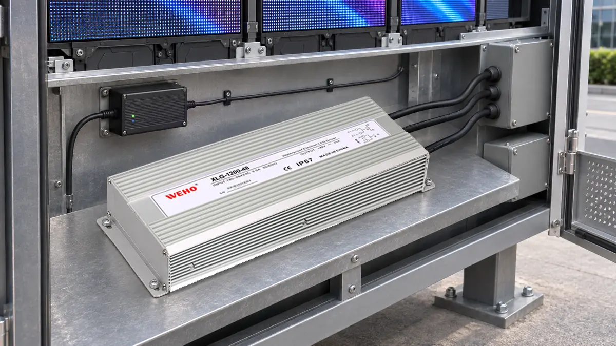
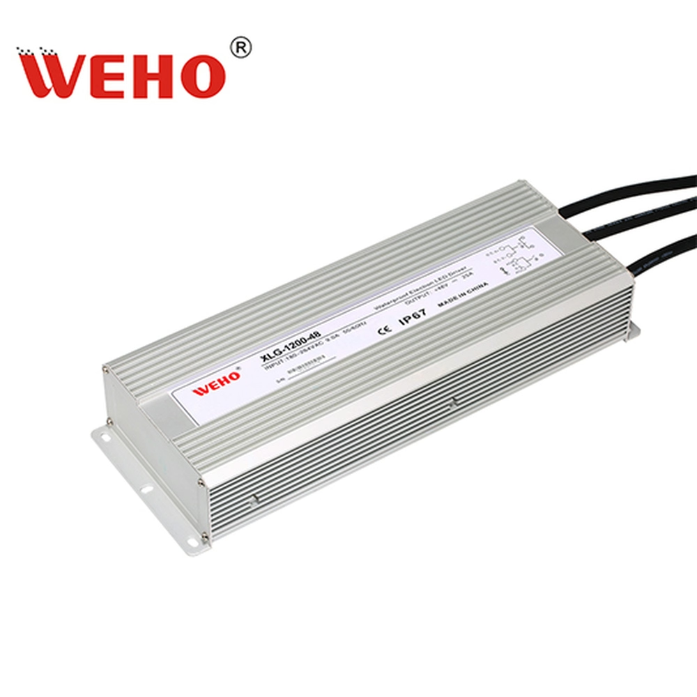
را WEHO XLG-1200-48 lighting source provides the product context for this review. The task is to identify the complete system's energy paths and define what “off” means at each boundary. It is not a claim that this driver generates, accepts or blocks current through any undocumented external path.
Separate Three Different Meanings of Off
An operating command can request no light output. A branch switch can interrupt a particular power conductor or circuit. A service-isolation procedure establishes the conditions required for the actual work. These outcomes should not share an unexplained “off” tick box.
Specify the intended outcome first. A dimming command can be entirely adequate for normal light control while being irrelevant to a maintenance-isolation decision. Likewise, opening a main branch supply can leave a controller powered from a separate auxiliary rail.
را XLG-1200 manufacturer specification lists the 48 V, 25 A variant and a 180–264 VAC input range. At the stated nominal output, 48 × 25 = 1200 W. These source identifiers do not define the internal circuit of a project-specific lighting controller or its powered-off input behavior.
| State name | Intended outcome | Evidence needed | Unanswered question |
|---|---|---|---|
| Lighting commanded off | No requested light output | Command and receiver response | Which electronics remain powered? |
| Main branch feed interrupted | One defined energy path opened | Actual circuit boundary and device duty | Are auxiliary or signal paths still present? |
| Controller unpowered | Its required supply rails absent | Rail and interface behavior under covered conditions | Can a connected signal energize a rail? |
| Prepared for service | Equipment-specific safe working condition | Approved all-source isolation and verification procedure | Which sources and stored energies must be controlled? |
Name the state in drawings, operator instructions and verification records. This avoids treating a successful no-light observation as evidence that a circuit is electrically isolated.
Trace Paths Through Interfaces, Not Only Power Cables
Start with the actual wiring diagram and list every connection crossing the branch boundary. Include controller power, data, enable signals, monitoring circuits and any separately powered accessory. An interface can connect two power domains even when the diagram visually separates their main supply boxes.
Texas Instruments' powered-off protection explanation shows how a signal can back-power a device through internal protection structures during a sequencing mismatch. That example establishes a possible mechanism in the documented IC arrangement; it does not prove that every lighting interface has the same path.
For each actual interface, obtain its permitted signal conditions when the receiving side is unpowered. Check the exact device revision and whether powered-off behavior is specified. Do not apply a protection feature from a similarly named interface component to an unspecified controller board.
An observed voltage also needs interpretation. A high-impedance meter reading can indicate a potential without describing the available current or permitted operating state. A faint indicator or a dark LED strip similarly does not quantify the source or prove absence of energy. Use a measurement plan suitable for the circuit and required decision.
Work Through an Alternate-Path Example
Consider a hypothetical lighting system with a 48 V main lighting bus, a separate 5 V control supply and a data interface entering a branch controller. Assume the design has an operating switch that interrupts the branch's main DC feed. No particular XLG-1200 internal feature or real controller pinout is represented.
In state A, the main feed and controller supply are both on. In state B, the main branch feed is opened through the approved arrangement while the upstream data equipment remains powered. The question is whether the actual receiving interface permits that state without unintended energization or overstress.
If a current path exists through the interface, the controller may not be in the unpowered state expected by the designer. That finding would belong to the interface and system review. It would not establish that the 48 V source's reverse-current protection failed, because its relevant behavior has not been identified by the observation.
Now consider state C, where all ordinary light commands request zero output but the main bus remains connected. The lamps may be dark while the controller and portions of the load remain powered as designed. State C can satisfy an operating requirement without satisfying any service-isolation requirement.
| Hypothetical state | Main branch feed | Auxiliary or signal domain | Required verification |
|---|---|---|---|
| A: normal operation | Connected | Powered as designed | Normal output and interface function |
| B: main feed absent | Opened at the defined boundary | Upstream equipment still powered | Permitted unpowered-receiver signal behavior |
| C: commanded zero light | Connected | Still powered | No-light performance, not isolation |
| D: planned service condition | Controlled by approved procedure | All relevant sources addressed | Equipment-specific isolation and verification record |
The table supplies questions and state definitions, not observed results. Its benefit is locating the evidence gap before an ambiguous “branch off” instruction reaches production or service personnel.

Swipe horizontally on a small screen, or open the full-size diagram.
Turn the Map Into a Verification Plan
- Draw the boundary being evaluated. Name the branch, controller and receiving load. Mark every conductor or interface crossing that boundary, including paths not supplied by the main lighting driver.
- List the available source states. Include normal operation, commanded zero output, loss of main power and any permitted partial-power condition. Do not create a state that the equipment's documents prohibit simply to complete a matrix.
- Obtain interface limits. Record allowed input voltage and powered-off conditions for the actual receiving components. If these are undocumented, ask the interface supplier or equipment design authority rather than inferring them from normal operation.
- Choose suitable observations. Define where voltage, current and functional state will be recorded. Preserve reference points and instrument loading so a result can be interpreted correctly.
- Perform the approved tests. Qualified personnel should follow the equipment's controlled procedure, especially where mains sources, multiple supplies or stored energy are present. A signal-path investigation does not replace that procedure.
- Release precise state descriptions. State which circuits remain powered in operating-off modes and which verification belongs to service preparation. Update the boundary map when a new controller or auxiliary device is added.
Use the branch energy-path worksheet to record each path, its source, permitted state and evidence. A blank reverse-current field remains an unanswered question, not a zero-current result.
Keep Mitigation Within Its Proven Scope
A system designer may consider an interface with documented powered-off behavior, an approved isolation arrangement or a revised sequence. Each solution needs evidence for the actual voltage domains and equipment requirements. This article does not prescribe a particular blocking diode, signal switch or safety function.
Opening an additional wire by experiment is not a substitute for identifying its function. A return, protective conductor or monitoring path may have consequences beyond the symptom under investigation. Changes belong in the equipment's design-control process and must be verified for the conditions they affect.
The separate reverse-current energy review addresses where returned load energy can go. This article adds the different question of how an auxiliary or signal domain can preserve an unexpected energized state after a main branch command changes.
Send WEHO the Source Boundary and the Interface Questions
For an XLG-1200-48 system inquiry, provide the source model, operating input, load schedule and complete branch diagram. Identify the exact behavior needed from the driver and separately identify questions belonging to the controller or interface supplier. Ask for the applicable product information without assuming reverse-current tolerance, output-channel independence or a remote-off function.
Engineering FAQ
Does no visible light mean the branch has no electrical energy?
No. A light-off command can leave the main bus, controller or auxiliary electronics energized. Use the actual circuit and the required state definition rather than visual light output to decide which paths remain active.
Does a signal connection always back-power an unpowered controller?
No. The behavior depends on the actual interface circuit and its powered-off specifications. Trace the connection and obtain the relevant component information before concluding that a path exists or that it is blocked.
Can the XLG-1200-48 product rating establish reverse-current tolerance?
No. Nominal output voltage, current and power do not establish a reverse-current allowance. Obtain the applicable manufacturer statement for the exact unit and keep the external interface's behavior separate.
Is opening the main branch feed sufficient for service?
Only the equipment's approved isolation and verification procedure can establish the required service condition. Main-feed interruption is one defined action; other sources, interfaces and stored energy must be addressed as the actual equipment requires.



