



Key Engineering Takeaways
- Accept a changing 12 V load against its voltage limits at the receiver, not just the power-supply terminals.
- Record minimum voltage, maximum voltage and event duration with the load transition that caused them.
- RSP-350-12 documentation lists 12 V and 29 A; those ratings do not establish a particular load-step waveform.
- Use the receiver's operating requirements and a suitable measurement plan to decide acceptance.
A Normal Average Reading Can Hide an Unacceptable Event
An OEM controller can reset during a load change while a handheld meter continues to show approximately 12 V. A different receiver may remain functional through the same event. The decision therefore requires both a captured voltage history and the actual receiver's acceptance criteria.
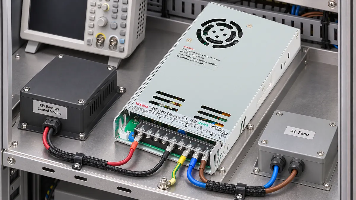
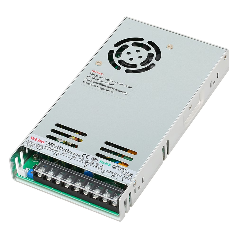
Le WEHO RSP-350-12 product page identifies the source considered here. The article's output is a receiver-voltage acceptance record, not a declaration that this supply supports an unspecified pulse load. A photograph, a wattage class and an average current reading cannot supply that missing evidence.
Define the Voltage Window Before Choosing the Event
Begin with the receiver's permitted supply range and any separately documented transient limits. Record the full receiving-device model and document revision. A nominal 12 V marking is an identity, not a complete minimum-and-maximum operating requirement.
Keep ordinary operating limits separate from absolute maximum ratings. The latter do not automatically describe a voltage at which normal function is guaranteed. If the receiver permits a short excursion, its allowed amplitude, duration and relevant conditions belong in the record rather than being inferred from a successful restart.
Le RSP-350W manufacturer specification lists 12 V and 0–29 A for the RSP-350-12. Multiplying the nominal values gives 12 × 29 = 348 W. This identifies the published nominal output point; it does not supply an overshoot limit, a recovery-time guarantee or an allowance for every possible current edge.
| Requirement | Where it applies | Evidence to record | Unresolved condition |
|---|---|---|---|
| Minimum operating voltage | Receiver supply terminals | Receiver specification and revision | Any permitted short interruption |
| Maximum operating voltage | Receiver supply terminals | Receiver operating limit | Whether a separate transient limit exists |
| Source operating condition | Power-supply output | Exact source, input, load and temperature | Applicable current and thermal boundaries |
| Dynamic load event | Actual equipment state transition | Current levels, edge, dwell and repetition | States not reproduced by the test |
A useful event comes from the equipment's actual switching states. Record the current before and after the transition, whether other branches switch at the same time, and what the receiver is doing during the event. An arbitrary laboratory square wave can be useful, but its relationship to the application must be explained.
Compare the Source and Receiver at the Same Event
A voltage excursion at the receiver can contain both source behavior and distribution effects. Measuring only the source can miss a cable or connector contribution; measuring only the receiver can make an upstream event harder to locate.
Where the approved measurement arrangement permits, capture both locations against a common time reference. Identify the reference points explicitly. A probe on the source's DC return and a probe on a different remote reference do not automatically describe the same differential voltage.
Keysight's transient-test overview describes controlled load changes and time-based capture of output voltage. For an equipment acceptance test, extend that discipline to the receiving terminals and keep the load event, voltage trace and instrument configuration together. Select suitable differential or isolated measurement methods where the circuit reference requires them.
The record should state probe type, bandwidth setting, sampling arrangement and trigger source. Avoid comparing a bandwidth-limited trace from one test with an unrestricted peak detector from another as though the difference proved that a product changed. The appropriate setup depends on the event and the requirement being evaluated.
Work Through a Receiver-Window Example
The following is a hypothetical engineering example, not an RSP-350-12 test. Assume an imaginary receiver must remain between 11.40 V and 12.60 V during the defined operating transition. Assume no exception for brief excursions has been specified.
For a steady 8 A branch and an assumed 0.060 Ω total distribution resistance, the simple resistive estimate is ΔV = I × R = 8 × 0.060 = 0.48 V. With 12.00 V at the source, the estimated receiver voltage is 12.00 − 0.48 = 11.52 V. That static estimate lies within the assumed window.
Now assume the event record shows a simultaneous source minimum of 11.82 V and receiver minimum of 11.34 V. The receiver minimum is 11.40 − 11.34 = 0.06 V below the example's lower limit. A satisfactory steady estimate does not cancel that event.
| Hypothetical record | Source voltage | Receiver voltage | Decision basis |
|---|---|---|---|
| Steady 8 A state | 12.00 V | 11.52 V estimated | Inside the assumed operating window |
| Captured load transition | 11.82 V minimum | 11.34 V minimum | Below the assumed 11.40 V limit |
| Captured release event | Value to record | Maximum and duration to record | Compare with the upper limit separately |
| Measurement confidence | Instrument and probe details | Uncertainty and event coverage | Resolve borderline outcomes before release |
The arithmetic establishes the example's nominal difference, not the certainty of a real measurement. A real decision also needs the measurement uncertainty and the equipment team's acceptance rule, particularly when a result lies close to the boundary. Do not invent a universal guard band from this 60 mV example.
A successful functional cycle is useful evidence, but it does not by itself authorize operation outside the receiver's specified range. Conversely, a captured minimum without a trustworthy reference or sufficient event coverage may require a corrected measurement before a product is rejected.

Swipe horizontally on a small screen, or open the full-size diagram.
Build a Test Record That Explains the Result
- List the relevant receivers. Record their voltage windows and document sources. Separate devices sharing the same nominal voltage when their lower limits or transient allowances differ.
- Define the transition. Capture the equipment command and resulting current state. Include coincident branch actions that the normal operating sequence allows, rather than testing one convenient isolated load only.
- Confirm measurement boundaries. Identify source and receiver points and verify the reference arrangement before energizing the controlled test. Electrical work and instrument connections must follow the equipment's approved procedure.
- Capture both edges. Record the load increase and load release, minimum and maximum voltage, event duration and any observed receiver response. A droop-only record leaves the high-voltage side unanswered.
- Make a bounded decision. Compare the traces with the actual operating requirements and uncertainty rule. State exactly which input, temperature, wiring and load conditions the result covers.
Download the receiver-voltage window worksheet to keep requirements and event records in one file. It includes space for observed values; its blank fields are not manufacturer limits.
If the receiver fails while the source remains within its relevant requirement, examine the distribution and receiver conditions before replacing the supply. The separate ripple acceptance matrix addresses ripple-specific criteria; a switching-event minimum is not automatically the same measurement.
Ask WEHO About the Required Operating Event
For an RSP-350-12 application review, send the receiver voltage limits, load-current transition, repetition pattern, AC input, ambient conditions and distribution arrangement. Include a trace with clearly identified measurement points if available. Ask for applicable model-revision data and the proposed verification conditions rather than requesting an unsupported “pulse rating.”
Engineering FAQ
Does a 12 V receiver always accept the RSP-350-12 output?
No. A nominal voltage match is only a starting point. Compare the receiver's actual operating window, load behavior and installation conditions with the documented source and the measured voltage at the receiving terminals.
Can an average meter reading prove that a brief voltage dip is acceptable?
No. An average reading can miss a short event. Use a measurement method suited to its duration, then compare the captured minimum and maximum with the receiver's documented limits and any allowed transient conditions.
Does 29 A establish a load-step recovery time?
No. The published output-current range does not establish the waveform for a particular load change. Recovery depends on the defined event and conditions, and requires applicable dynamic information or a controlled application test.
Should the output be raised until the lowest receiver voltage passes?
Not without checking the whole operating window. Raising a setpoint can also increase voltage at lightly loaded receivers or during load release. Any adjustment must remain within all applicable source and receiver limits and be verified across the relevant states.



