



- An RTD dissipates I²R power from its measuring current, so the element can run warmer than the process.
- Estimate self-heating with the probe’s dissipation data for its actual installation medium.
- Reducing current changes the measurement signal as well as heating; verify the complete error budget.
- Do not assume the ordered TX4-W exposes an adjustable excitation-current setting.

Why a stable display may still be biased
An OEM compares two RTD readouts in the same bath and finds a repeatable difference. Replacing the sensor or adding an offset may hide the symptom without explaining whether the element is being heated by the measurement itself. Separate excitation power, thermal dissipation and actual process temperature before changing calibration records.
Le TX4-W temperature-controller reference provides the product context for this review. The front display cannot reveal measuring current, probe dissipation or the actual temperature error. Those quantities require the ordered controller documentation and the installed probe's evidence.
Define electrical heating and thermal removal separately
An RTD requires excitation to convert resistance into a measurable electrical signal. NI's RTD measurement documentation identifies self-heating as a measurement concern and relates temperature rise to dissipated power and a dissipation constant. The relevant constant describes the probe's ability to transfer heat into its surroundings.
For a steady approximation, use P = I² × R and ΔT = P / E. P is the element power, I is the actual measuring current, R is the element resistance at the operating point, and E is the dissipation constant. If P is expressed in milliwatts, E must be expressed in milliwatts per degree Celsius.
Some manufacturers instead state a self-heating coefficient in degrees Celsius per milliwatt. That coefficient multiplies power rather than dividing it; its numerical value is the reciprocal of E under the same conditions. Check the units before importing a supplier value into the calculation.
A dissipation figure measured in moving liquid does not automatically apply to still air or a loosely fitted thermowell. Probe construction, insertion, contact and local flow influence the thermal path. Record the test medium and installation condition beside the figure so that a catalog number does not become a universal correction.
Le Texas Instruments RTD measurement guide discusses the tradeoff between excitation signal and self-heating. That design principle does not establish the excitation circuit or configurable options of a WEHO controller. Obtain those details separately for the exact ordered unit.
Calculate a hypothetical current-and-medium budget
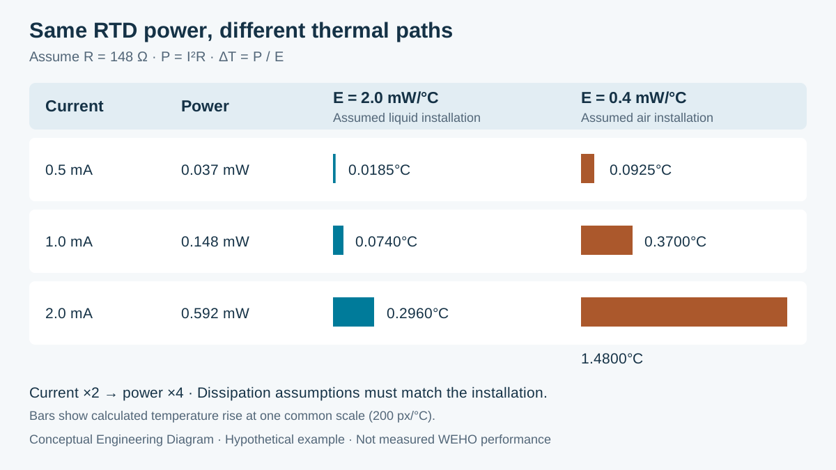
Assume a probe has R = 148 Ω at the operating point. For illustration only, use E = 2.0 mW/°C in one qualified liquid installation and E = 0.4 mW/°C in a second air installation. These invented thermal values are not TX4-W specifications or ratings of any particular probe.
At 1.0 mA, P = (0.001 A)² × 148 Ω = 0.000148 W, or 0.148 mW. The estimated rise is 0.148 / 2.0 = 0.074°C in the first installation. In the second installation, the same electrical power gives 0.148 / 0.4 = 0.370°C.
Doubling current to 2.0 mA produces 0.592 mW, four times the original power. The corresponding rises become 0.296°C and 1.480°C. Halving current to 0.5 mA gives 0.037 mW, yielding 0.0185°C and 0.0925°C respectively.
Suppose the project allocates at most 0.10°C to steady self-heating at this point. Under these assumptions, the 1.0 mA liquid case fits that allocation while the 1.0 mA air case does not. This is only a component of an uncertainty budget; meeting it does not establish total measurement accuracy.
Swipe horizontally on a small screen, or open the full-size diagram.
| Excitation current | Element power | Rise at 2.0 mW/°C | Rise at 0.4 mW/°C |
|---|---|---|---|
| 0.5 mA | 0.037 mW | 0.0185°C | 0.0925°C |
| 1.0 mA | 0.148 mW | 0.0740°C | 0.3700°C |
| 2.0 mA | 0.592 mW | 0.2960°C | 1.4800°C |
The table also explains why a satisfactory bath comparison may not transfer to the machine's actual sensing pocket. The electrical circuit can remain unchanged while the thermal path becomes weaker. Reproduce the intended mounting and medium before using a self-heating estimate as a release criterion.
Build an evidence budget instead of a blanket offset
Self-heating is one possible positive element-temperature bias, not a universal explanation for a high display reading. Curve selection, lead effects, sensor tolerance, input electronics, reference uncertainty and thermal gradients can all contribute. Beckhoff's RTD self-heating explanation provides another manufacturer treatment of the excitation effect without establishing the characteristics of a TX4 input.
Use the maximum relevant sensor resistance and actual excitation behavior over the operating range. Where excitation is pulsed or changes during conversion, a constant-current steady estimate may be insufficient. Record the waveform information supplied by the input manufacturer and ask whether the probe's thermal response makes average, peak or another documented treatment appropriate.
Le TX4-S measurement-chain article addresses thermocouples rather than RTD excitation. Keep its reference-chain discipline, but do not transfer thermocouple compensation rules to a resistance sensor. Document which error mechanism each verification step actually tests.
Verify self-heating without assuming current is adjustable
- Identify the input and probe. Record the complete controller configuration, RTD curve, connection and probe part number. Confirm their compatibility using the applicable instructions; the TX4 series manual is a starting point rather than evidence of an adjustable measuring-current parameter.
- Obtain excitation evidence. Request the applicable measuring-current value, tolerance and any pulsed behavior. Record the manufacturer's stated conditions, then verify that the information applies to the actual input mode instead of borrowing a value from another instrument.
- Obtain thermal evidence. Record the probe's dissipation specification, medium, immersion and flow conditions. If the process installation differs, obtain relevant supplier data or plan a qualified comparison rather than treating the catalog value as installed performance.
- Calculate the allocation. Record current, resistance, units and the selected dissipation basis. Compare the resulting contribution with the project's allotted uncertainty at each relevant operating condition; retain the other error contributions separately.
- Validate the assembled arrangement. Record stabilized reference and controller readings under the intended thermal conditions. Where an approved external instrument supports multiple excitation currents, a specialist may compare current-dependent readings under a defined procedure; this is not an instruction to alter unsupported TX4 settings.
A current-dependent comparison needs a stable reference and repeatable thermal conditions. Changing instruments can also change lead compensation, conversion curves and input accuracy, so a difference between instruments cannot automatically be attributed entirely to self-heating. Control or quantify those influences before drawing the conclusion.
Do not use a fitted offset to compensate for a variable thermal path without establishing its range of validity. A correction obtained at one flow rate, insertion depth or temperature can fail elsewhere. The useful release record identifies both the accepted arrangement and the conditions that require reassessment.
Ask WEHO for the input details that close the budget
Send the TX4-W input configuration enquiry with the complete unit label, RTD curve, probe construction, operating range and installation medium. Include the allocated self-heating error and ask for the applicable excitation information. Provide the probe supplier's dissipation evidence so that the electrical and thermal assumptions can be evaluated together.
Engineering FAQ
Does an RTD measure its own temperature or the surrounding process?
An RTD responds to its element temperature, which can differ from the surrounding process. Excitation heating and the thermal path both influence that difference. Appropriate installation and an uncertainty budget are needed to interpret the reported temperature.
Does doubling RTD measuring current double self-heating?
Doubling current quadruples I²R power when resistance is held constant. The resulting temperature rise also depends on heat dissipation and the validity of the thermal model. A change in medium can matter as much as a change in current.
Can I use a water-bath dissipation value for still air?
Only use that value if its applicability to the air installation is established. Different heat-transfer conditions can produce a different temperature rise for the same electrical power. Obtain installation-relevant evidence rather than copying the more favorable figure.
Can I reduce TX4-W excitation current from its front panel?
Do not assume an adjustable excitation setting is available. Confirm the applicable input configuration and instructions for the ordered unit. If adjustment is not documented, assess the supported input and probe arrangement rather than inventing a parameter change.


