



A Q-60W analytical instrument power project needs a receiver-interface review before the supply harness is released. The photographed WEHO Q-60B identifies four outputs and a COM terminal, but those markings alone do not establish that a measurement board accepts their voltage, reference connection or startup behavior. Build a receiver-by-receiver compatibility matrix, then obtain the missing acceptance evidence.
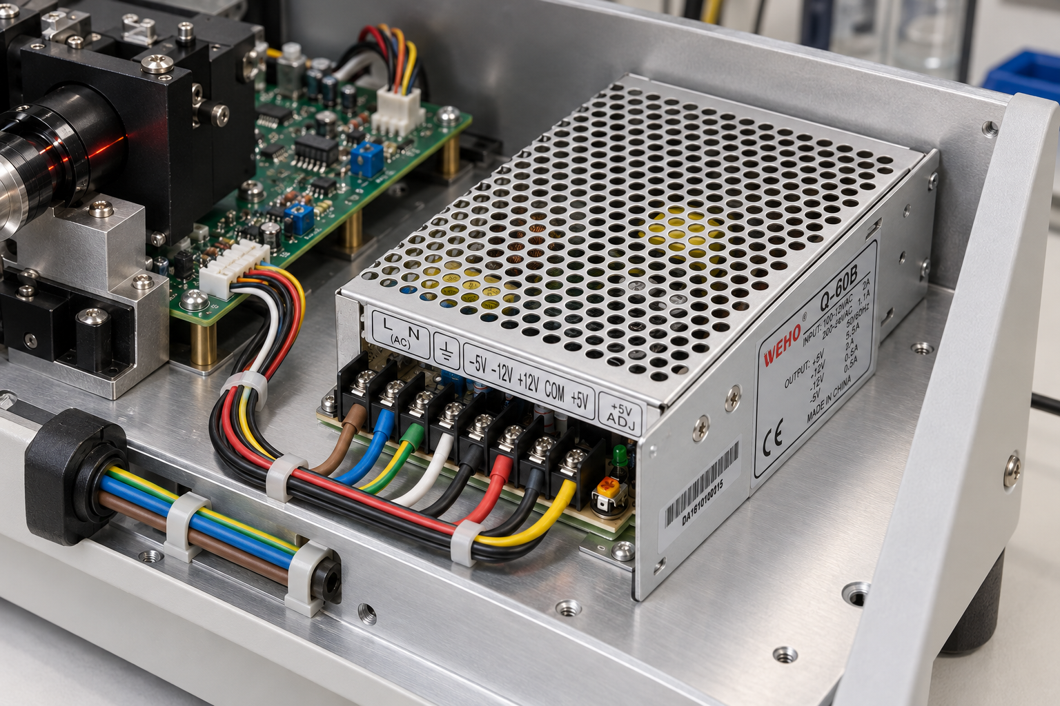
Start with the receiving instrument, not a list of available rails
Separate each receiver function in the instrument: a logic board, an analog conditioning stage, a sensor interface and any separately powered load. Record the receiver manufacturer’s required supply terminals and their reference definition. Do not infer a need for every Q-60B output merely because the terminals exist.
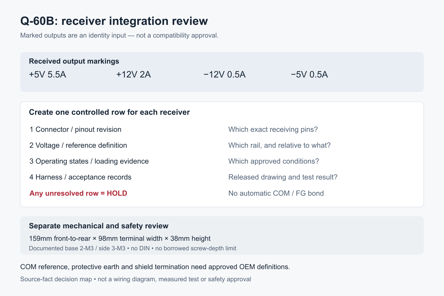
The selected physical specimen is marked +5V 5.5A, +12V 2A, −12V 0.5A and −5V 0.5A. These are the received nameplate identities, not four interchangeable current allowances. Its front terminal sequence, viewed from the terminal edge, is L, N, protective-earth symbol, −5V, −12V, +12V, COM, +5V. COM is an output-reference terminal; it must not be treated as another positive output or automatically bonded to protective earth.
Use a receiver compatibility matrix
| Receiver record | Evidence required before release | Do not substitute |
|---|---|---|
| Connector and pin identity | Controlled receiving-board pinout, connector orientation and harness drawing revision | A similar connector shell or a wire color |
| Required voltage and reference | Receiver supply limits and its documented reference connection, mapped to the exact Q-60B terminal | The instrument’s generic “12V” description |
| Load and operating states | Receiver steady-state demand, startup demand and simultaneous operating conditions; corresponding approved supply conditions | A sum of nominal nameplate currents |
| Reference and chassis arrangement | OEM definition of signal reference, shield termination and protective-earth arrangement | An assumption that COM, shield and FG are the same node |
| Acceptance test | Written limits and recorded results at the receiving connector under the specified operating states | A green indicator or a generated application image |
A useful row contains the receiver identifier, required pins, selected supply terminal, harness identifier, evidence revision and release status. Mark unresolved rows “hold.” This keeps a provisional mechanical arrangement from being mistaken for an approved electrical design.
Keep the input and safety review separate
The actual nameplate carries 100–120VAC 2A / 200–240VAC 1.1A, 50/60Hz. Copy the received markings into the equipment record, but do not use this interface article as an input-range or safety-qualification decision. The public catalog and controlled sheet contain unresolved auxiliary differences in current-range, DC-input, temperature and withstand-voltage fields. Those fields require a reconciled, applicable revision before a system operating specification can be released.
The input L and N terminals, protective-earth connection and applicable equipment safety requirements belong in their own approved drawing and verification procedure. The presence of negative outputs does not establish isolated channels, a required earth bond or a permitted series connection.
Check the mechanical receiving space
The complete Q-60 drawing gives 159mm front-to-rear length × 98mm terminal-row width × 38mm height, with two underside M3 et three side M3 mounting interfaces. It does not specify a screw engagement-depth limit here, so do not copy one from a different series. Use only the documented case interfaces and obtain the applicable fastener instruction.
This fanless sheet-metal product is not a DIN-rail supply. Preserve access to the actual bare screw-clamp entries and the separate +5V ADJ control. Keep the electrical bay dry, separate from sample paths, and evaluate wiring access and thermal arrangement as part of the instrument design. No fixed ventilation clearance or temperature capability is established by this article.
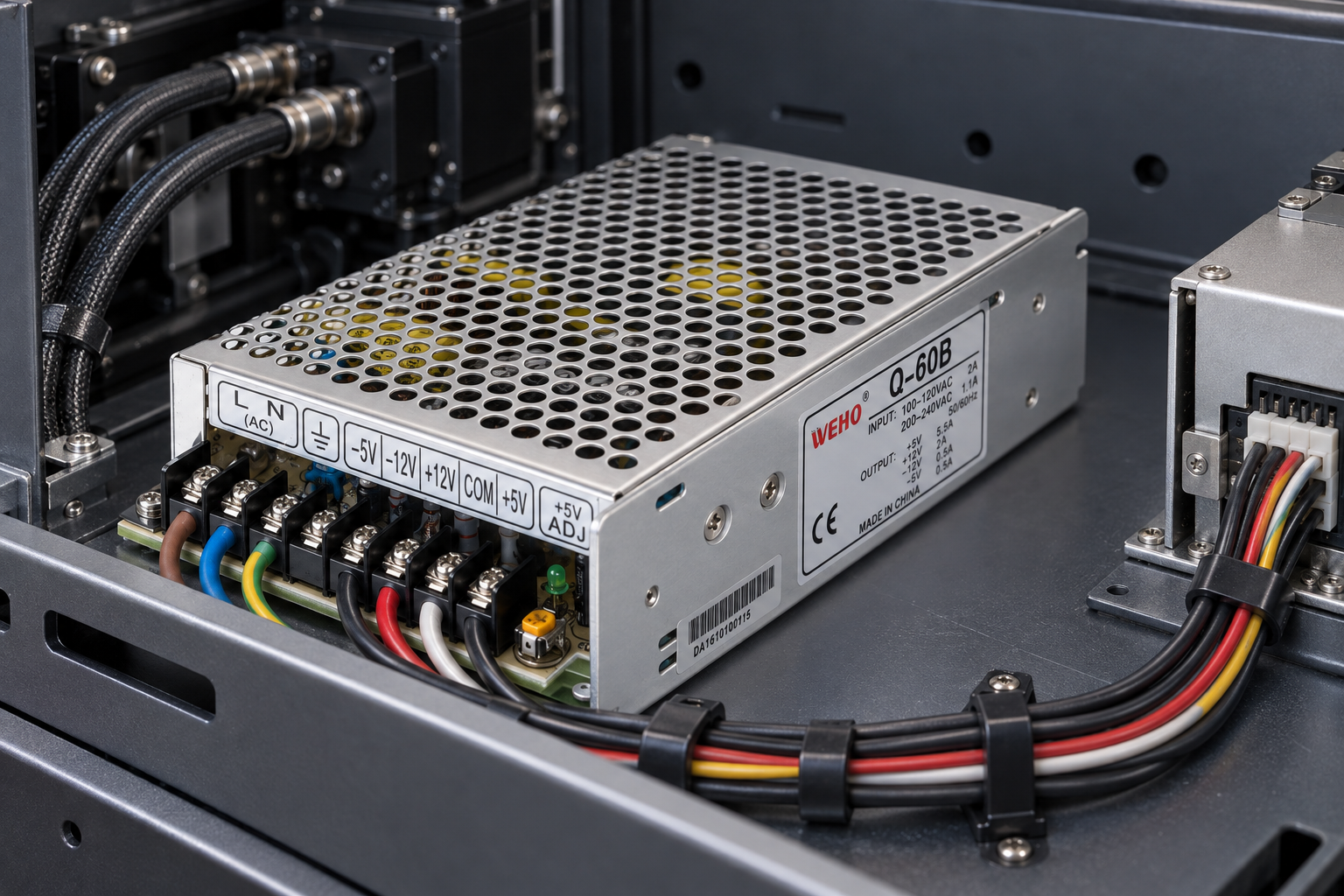
Release the harness only when the receiving records agree
Before production, reconcile the exact received model and document revision, approve each receiver-matrix row, release the harness drawing, and record the required tests. A failed or unresolved row remains a hold point even if the enclosure fits. An OEM RFQ should therefore request the exact Q-60B revision and the missing electrical or mounting instructions, not just “a four-output supply.”
Frequently asked questions
Does the Q-60B label approve an analytical instrument design?
No. It identifies the received outputs. Receiver limits, reference arrangements, operating conditions and acceptance tests must be established independently.
Can I connect COM to the chassis because FG is provided?
Do not infer that connection from the labels. Follow the approved OEM reference and protective-earth design; this source does not establish a universal bonding rule.
Can an unused output be repurposed as an isolated rail?
No isolation or repurposing permission follows from an unused terminal. Obtain the applicable circuit documentation and receiver approval.
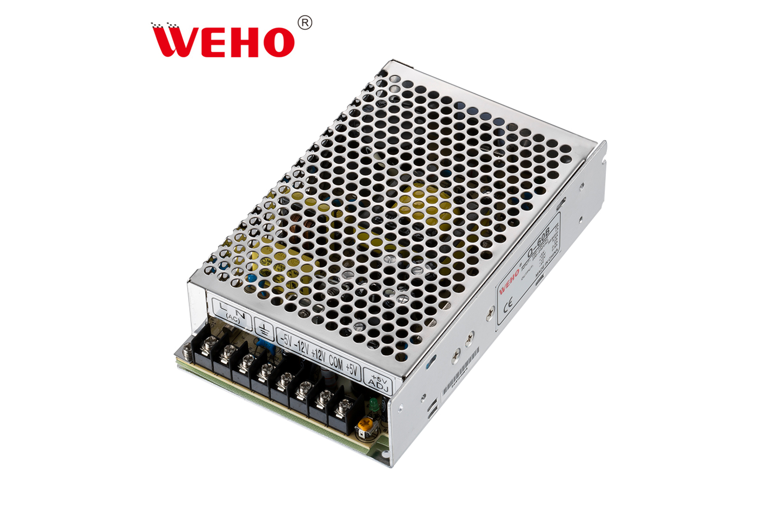
Product reference
See the official WEHO Q-60W quad-output product page. The application illustrations and receiver matrix are engineering-review aids, not test results or a wiring authorization.




