Verify the neutral/earth arrangement and protective-device requirements separately for every permitted inverter operating mode. Do not add a neutral-to-earth link or assume one exists because the unit produces a pure sine wave.
For an equipment integrator considering the WEHO WHPU-1000 inverter/charger family, the next decision is whether the exact unit and installation documents establish a complete protection scheme. The public product table reviewed here does not define its internal neutral/earth bond, switched-neutral arrangement or a transfer topology.
Identify the exact unit before drawing a protection scheme
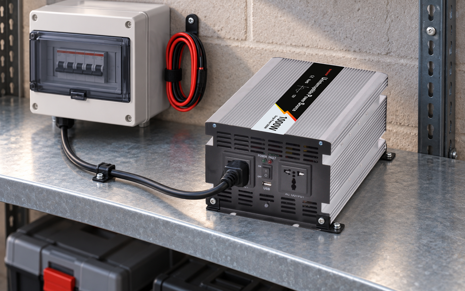
Record the ordered DC input variant, AC output voltage/frequency, socket arrangement and revision. The WHPU-1000 page lists 12 V and 24 V input variants and several AC output options. A photograph showing the family is not enough to establish which internal arrangement is supplied.
Request the controlled installation manual, terminal identification, chassis/PE requirements and an explanation of the neutral arrangement in every supported mode. If AC charging and AC feed-through are both proposed, confirm which functions the exact product actually provides and how they interact. A charger function alone does not prove an automatic bypass or transfer switch.
The installation designer must determine the applicable local protective arrangement. Keep that design decision separate from the marketing waveform description.
List operating modes and transitions explicitly
Victron’s explanation of inverter/charger earthing illustrates why modes matter: its documented equipment can change internal connections when it changes between inverting and source-fed operation. That is a manufacturer-specific example of the documentation needed. It is not evidence that WHPU-1000 uses the same relay, bonding logic or AC/DC isolation construction.
| Proposed state | Confirm with the exact unit documents | Record for the installation |
|---|---|---|
| Battery inverting | Output conductor identification, chassis connection and permitted neutral/earth arrangement. | Source identity and the specified protection path for this state. |
| AC charging | Whether the AC input also energizes an output, and under what conditions. | Which circuits remain live and which protection arrangement applies. |
| Feed-through or bypass, if provided | Connected/switched conductors and source requirements. | Upstream/downstream relationships and permitted configuration. |
| Source loss and restoration | Supported transition behavior and switching sequence. | Any intermediate states that the design must address. |
| Off/service state | Isolation provisions and remaining energized circuits. | Applicable isolation and verification procedure. |
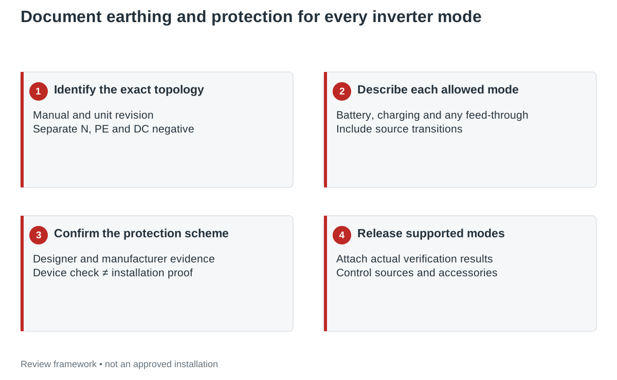
Specify RCD evidence for the complete circuit
A residual-current device detects an imbalance in the conductors it monitors. Its type, location and performance must be appropriate to the actual source and connected equipment. Obtain the inverter manufacturer’s requirements and the installation designer’s protection assessment rather than selecting a device solely by its rated current.
Separate the RCD’s own functional test from verification of the installed protective arrangement. The IET’s RCD testing explanation describes a test-button circuit that creates an internal imbalance without sending test current to earth. A successful button operation cannot, by itself, establish the installation’s PE continuity or the intended fault path in another source mode.
Have qualified personnel establish the required installation tests and acceptance criteria under the applicable instructions. This guide does not prescribe a bond location, RCD type or test connection for WHPU-1000. Those decisions require the missing exact-unit and system information.
A mains-fed check does not cover battery operation
Illustrative handoff gap: a project file contains a successful RCD button check while an AC source is available. It also contains a WHPU-1000 product page stating pure-sine-wave output. The file has no documented neutral arrangement for battery inverting and no evaluation of that mode’s protective scheme.
Keep the AC-source check as evidence for what was actually checked. Add a separate request for the inverter-mode connection information and a corresponding installation verification plan. Do not mark battery operation accepted by analogy, and do not install an improvised bond to make an informal test behave as expected.
If the product instructions do not support the required installation, reconsider the equipment or overall design. An undefined protection arrangement is a specific design gap; it is not resolved by a larger inverter wattage or a different waveform label.
Include transitions, accessories and alternate sources
A mode table is incomplete if it covers only the stable endpoints. Identify every permitted source change, external transfer device and alternate AC source. Ask which conductors are switched, which remain connected and whether the approved protection arrangement changes during the transition.
Keep protective earth, AC neutral and DC negative separately identified in the documents. Do not assume that the DC negative may be bonded to chassis because another inverter manual allows it. The exact isolation construction and system requirements must support any such connection.
Review extensions, distribution boards and auxiliary loads as part of the intended configuration. They can change the circuit being protected even when the inverter itself is unchanged. Retain their identities and the applicable connection requirements in the final record.
Hand over a mode-specific protection record
Use the blank inverter neutral/earth and RCD mode record to organize manufacturer answers, the designer’s decisions and the actual verification results. Mark a mode supported only when its documentation and required evaluation are complete. A proposed but unsupported mode should remain outside the released operating instructions.
Tie the record to the inverter revision, external switching equipment, protection devices and allowed sources. Reassess affected states after a change. For WHPU-1000, this article provides a disciplined request and review method; it does not claim an internal bond, transfer arrangement or completed installation approval.
Use the project record
Open the blank Inverter neutral/earth and RCD operating-mode record to record your conditions, evidence and decisions. The worksheet contains no pre-approved result.
Request the earthing and mode information for your unit
Send WEHO the exact WHPU-1000 configuration, destination requirements, proposed AC/DC sources, external switching equipment and intended operating modes. Request the installation manual and mode-specific neutral, chassis, protective-earth and RCD requirements before finalizing the system.