Evaluate central 48 V to 12 V conversion when one serviceable location and shared 12 V distribution fit the equipment; evaluate local conversion when shorter high-current 12 V connections justify separate stages. Compare cable losses, converter operating loads and common failure points before choosing the arrangement. Local conversion does not by itself establish branch independence or redundancy.
Compare the same load locations and functional requirements. A module rating is only part of that comparison: input wiring, return connections, branch protection, mounting and maintenance access determine whether the architecture works in the equipment.
Article sections
Draw both conversion locations before comparing parts
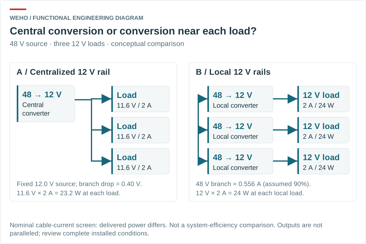
In a centralized arrangement, the 48 V source feeds one converter, followed by individual 12 V branches. In a distributed arrangement, separate 48 V branches feed converters near their respective 12 V loads. In the second case, each output serves its own load; the outputs are not connected in parallel.
| Architecture item | Central 12 V rail | Local conversion |
|---|---|---|
| Long branch normally carries | 12 V load current | 48 V converter input current |
| Power conversion location | One accessible central location | Near each load, with multiple thermal locations |
| Common dependencies | 48 V source, central converter and shared distribution segments | 48 V source and any shared upstream segments remain common |
| Service task | Central converter may affect all loads | Local replacement may affect one branch, if disconnection is controlled |
TI’s power-distribution architecture seminar describes centralized, distributed and intermediate-bus approaches. Its example products and isolation arrangements are not specifications for a WEHO module. The useful design question here is where conversion, distribution and functional boundaries are placed.
Screen branch current with three hypothetical loads
Assume three nominal 12 V loads, each drawing 2 A, at separate equipment locations. For a first wiring comparison, each long cable has 0.20 Ω total loop resistance, including its outward and return conductors. Assume 90% conversion efficiency for the local stages at the stated load. These are illustrative assumptions, not WH-C481210 measurements.
Use nominal voltages for the initial input-current estimate: each local converter supplies 24 W, so input current is approximately 24 W ÷(48 V ×0.90)=0.556 A. This approximation neglects the small reduction of input voltage along that 48 V branch.
| Long-cable quantity | Central 12 V distribution | 48 V distribution with local conversion |
|---|---|---|
| Estimated current per branch | 2 A | 0.556 A |
| Voltage drop per branch, I×R | 0.400 V | 0.111 V approximately |
| Cable loss per branch, I²R | 0.800 W | 0.0617 W approximately |
| Total loss in three long cables | 2.40 W | 0.185 W approximately |
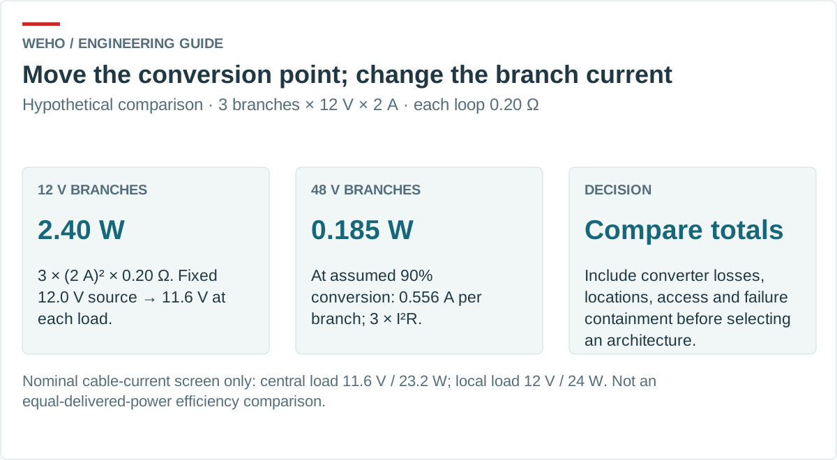
This is a cable-current screen, not an equal-delivered-power efficiency test. With exactly 12.0 V at the central branch input and a constant 2 A load, the load receives 11.6 V and 23.2 W; a local converter maintaining 12.0 V would deliver 24 W. The equipment’s permitted load-voltage range determines whether either result is acceptable. Do not silently assume a fixed 12 V module can be adjusted to compensate the drop.
If a branch instead behaves as a constant-power 24 W load, use a separate static model: (12 − 0.20 I) × I = 24. The lower-current solution is about 2.072 A, giving approximately 11.586 V at the load and 0.858 W cable loss per branch. That differs from the 2 A constant-current screen above. The equation describes a resistive steady state only; it does not establish control stability or acceptable equipment operation at that voltage.
For final budgets, use actual converter-terminal voltages, measured efficiency at each operating point and the full input/output tolerance. Multiple lightly loaded modules can consume more total power than a central stage. A lower long-cable loss alone does not decide the system energy result. The upstream current and harness-loss budget separates converter input power from external wiring loss; apply that method at the named boundaries of this 48 V system.
Define what happens when one branch fails
List the components shared by all loads. Moving conversion downstream does not remove an upstream source, connector or trunk cable as a common failure point. It also does not prevent an input fault in a local converter from pulling down a shared bus.
| Event to review | Central arrangement | Distributed arrangement |
|---|---|---|
| One load short | Check branch protection and central-source response | Check the local output response and its effect on the 48 V source |
| Converter input fault | One converter and its source protection are involved | Each local input needs a defined fault boundary |
| Loss of the common 48 V source | All dependent loads are affected | All dependent loads are still affected |
| Removing one subassembly | Define its branch disconnection | Define both 48 V input and 12 V load-side connections |
Separate converters serving separate loads are not an N+1 system. Establish source protection, restart behavior and the equipment’s permitted degraded mode with the intended assembly. Do not infer these from the module count.
Review WH-C481210 as an architecture candidate
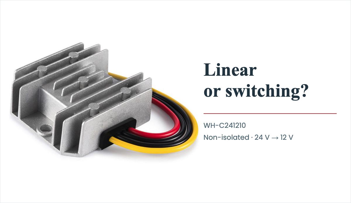
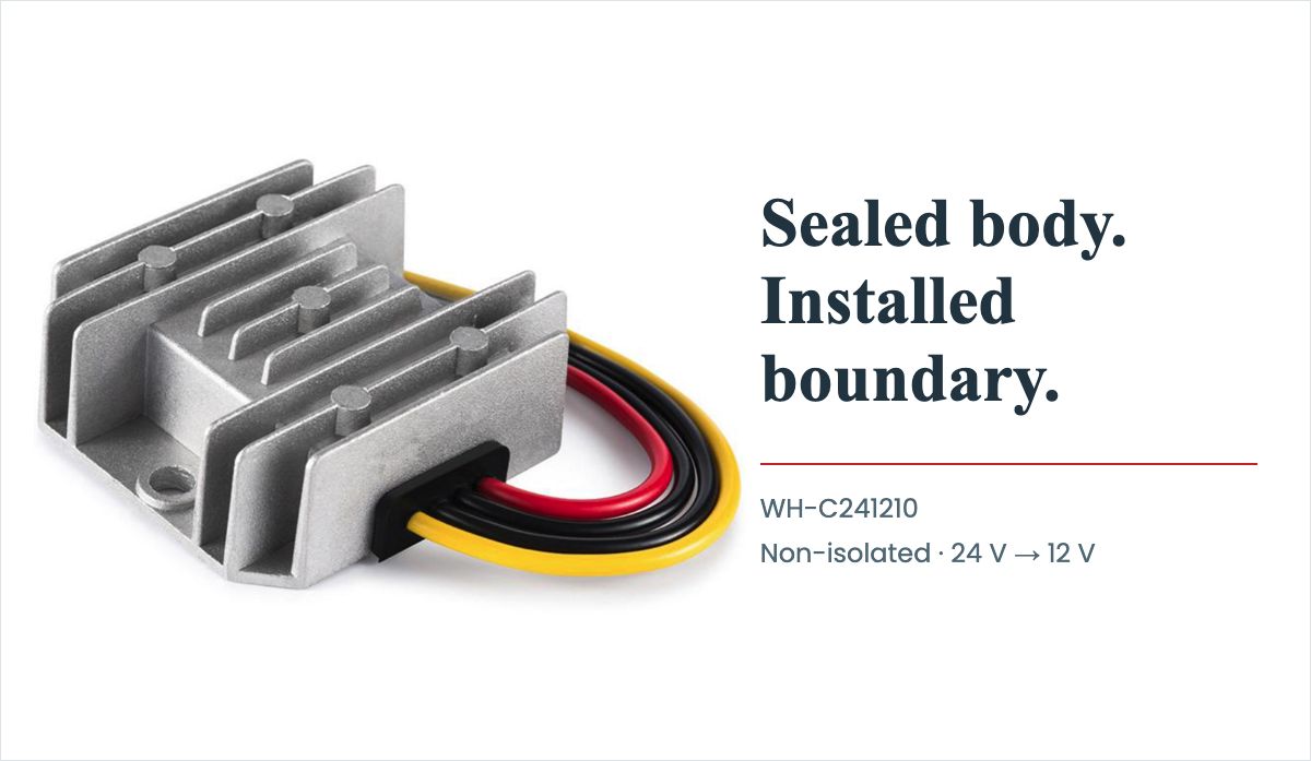
The WEHO WH-C481210 48 V to 12 V converter product page lists 30–60 VDC input and 12 V / 10 A output and explicitly identifies a non-isolated input/output relationship. Its stated common-negative connection means that local conversion does not create separate electrical references.
Those entries establish a documentation candidate, not approval of the entire 48 V system. Confirm the actual bus polarity, operating range and transients. A nominal 48 V battery system or a telecom negative 48 V distribution system is not approved merely because its label contains 48 V.
Using the published 120 W rating only as an arithmetic reference, the original nominal 72 W central-stage output corresponds to 60% load, while a local stage delivering 24 W corresponds to 20%. Compare efficiency and temperature evidence at those different operating points. Three lightly loaded 120 W stages should not be evaluated with a full-load efficiency assumption. Ask whether an appropriately rated local option can meet each branch requirement; no smaller model or installation approval is established here.
Obtain the applicable controlled specification, thermal conditions, mounting information and fault-response data before selection. The reviewed product table does not establish the complete conditions needed to rate multiple units at different local temperatures or to guarantee branch independence.
Check return paths, mounting and access together
Draw the return conductors and signal cables between subassemblies, particularly where every converter is non-isolated. Independent positive branches can still share a conductive negative network. Record where an external controller, communication cable or chassis connection creates another path.
Then compare physical installation. A central stage may be easier to cool and replace; local stages may have shorter 12 V connections but less airflow or access. Include connector mating, cable strain relief and the space needed to service each unit. Multiple module locations also create more locations for identification and inspection.
Use the real source and representative branches for functional checks. Apply the agreed load changes, permitted branch disconnections and restart sequence. Record the behavior of unaffected loads as well as the branch being changed; an architecture claim should describe those dependencies explicitly.
Send a distribution drawing with the inquiry
A useful decision record combines load locations, current in each rail, cable-loop resistance, minimum load voltage, thermal locations, shared dependencies and required recovery behavior. Compare part count and service cost only after the electrical boundaries are clear.
Send WEHO your 48 V distribution and 12 V load layout with the actual source envelope, individual loads, cable lengths, mounting conditions and required behavior during a branch fault. Request the exact model documentation needed to compare central and local conversion.