एक EFT test evaluates equipment immunity to repetitive electrical fast transients, also called burst disturbances. For an OEM integrating a power supply, a useful test plan covers the equipment’s relevant ports and operating modes, then records what the powered functions do during and after exposure.
Define acceptable system behavior before testing. A steady power-supply indicator does not show whether the controller reset, communications stopped, or a stored setting changed. The integration engineer’s decision is whether the specified assembly meets its agreed functional requirements in the documented test configuration.
Article sections
Separate the disturbance from the acceptance decision
IEC 61000-4-4:2012 provides a basic EMC reference for evaluating electrical fast-transient/burst immunity at supply, signal, control, and earth ports. Record the edition required by the applicable product standard or contract. A standard number without its edition, test conditions, and outcome is an incomplete requirement.
EFT is distinct from an equipment-level electrostatic-discharge test or a surge test, as shown in TI’s overview of system transient standards. A report for one phenomenon does not establish performance under the others. Keep the test matrix and findings separate, even when one laboratory performs all three in the same campaign.
The appropriate severity, applicable ports, and performance criteria need to be established for the actual equipment and its governing requirements. This article proposes a planning and evidence structure; it does not assign a universal voltage, waveform program, exposure time, or pass criterion to every industrial power supply.
Freeze the assembly and its port map
Document the configuration being qualified: power-supply model and revision, input source, connected load, enclosure, grounding and bonding arrangement, filters, cable types and lengths, shield terminations, and firmware. If an auxiliary unit is needed, identify its role and how it is kept from obscuring the equipment’s behavior.
Map physical interfaces before deciding which tests apply. An external DC input, an internally wired DC rail, and a long external sensor cable have different places in the equipment boundary. Have the laboratory and responsible EMC engineer agree the applicable treatment instead of selecting ports solely because a terminal is labeled “24 V.”
| Port or function | Planning information | Evidence to retain |
|---|---|---|
| AC or DC supply port | Source, operating input, loading, protection, and applicable coupling method | Port identity, test-program reference, setup photographs, and rail/function observations |
| External signal or control cable | Interface use, representative cable, termination, shield, and active traffic | Cable route, exposure arrangement, error counters, and application result |
| Protective-earth and chassis connections | Installed bonding arrangement and required reference-plane relationship | Photographs and the controlled setup description |
| Dependent powered function | Controller, communication, display, or output state that matters to the application | Monitoring method, behavior during exposure, and recovery outcome |
View full diagram ↗
Coupling and setup are part of the result. AMETEK CTS’s burst-waveform verification note (Japanese) explains that grounding affects the burst characteristics delivered to the equipment and separately discusses verification of the coupling network and capacitive clamp. Keep the actual coupling arrangement, grounding and reference-plane relationship, and relevant equipment-verification record with the test. A generator-front-panel photograph cannot capture those conditions for a repeat comparison.
Identify NDR-240-24 within the EFT configuration
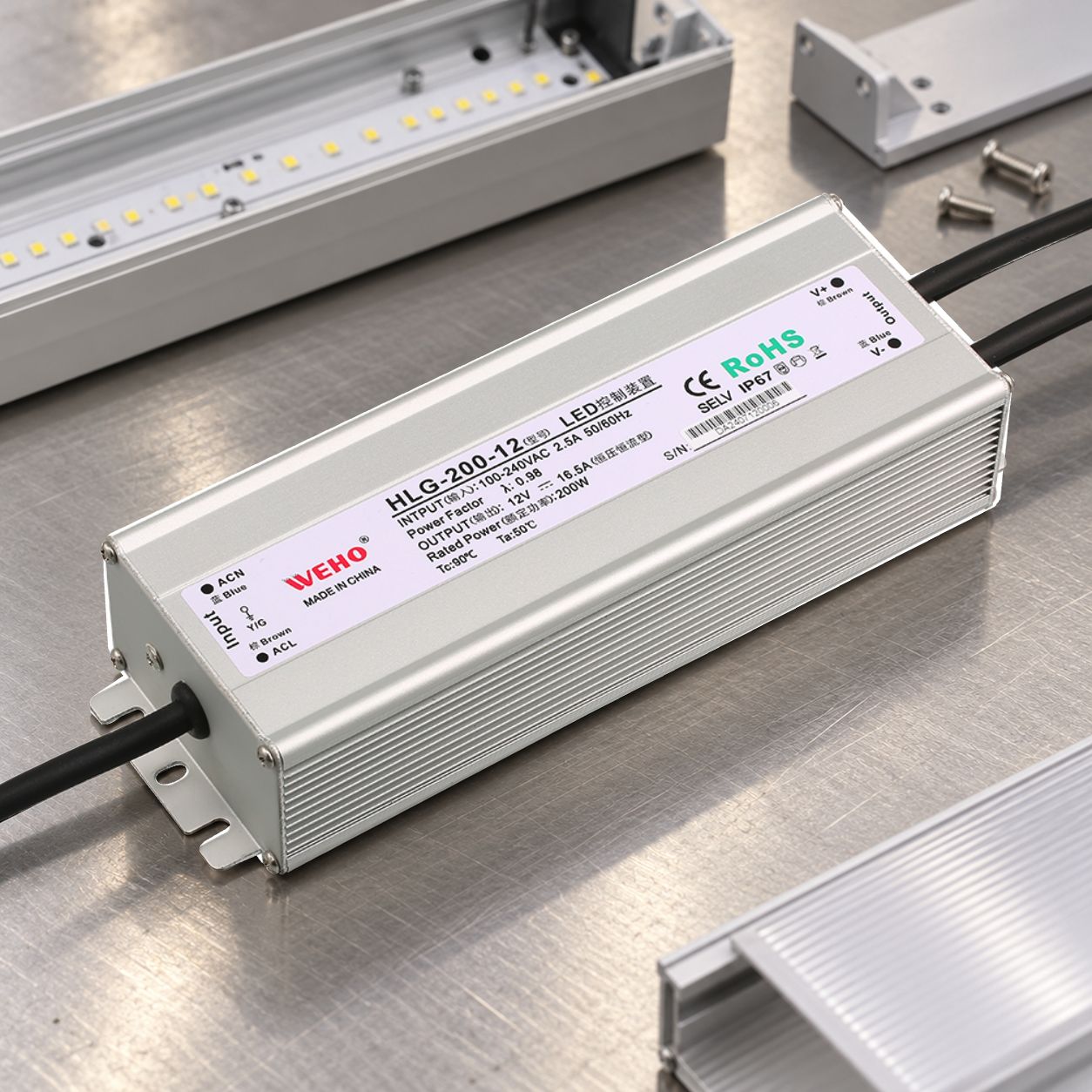
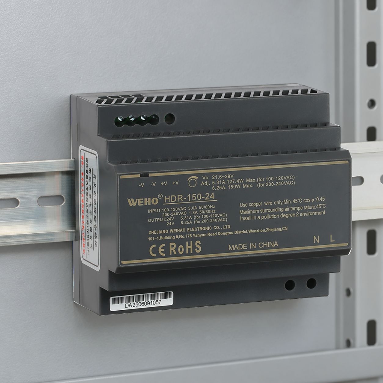
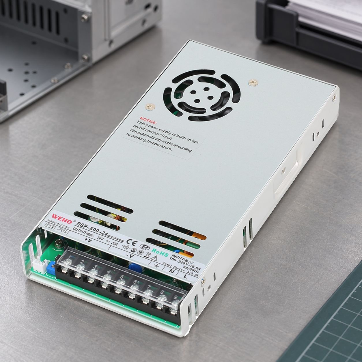
If a proposed control cabinet uses the WEHO NDR-240-24 DIN rail supply for its internal control rail, give that source a stable identifier in the equipment port map. The NDR-240 specification lists 24 V, 0–10 A output and an 85–264 V AC input range. Use those as starting points for the electrical review, then confirm the conditions permitted for the actual input, load and installation. Retain the exact sample marking and applicable specification revision beside the upstream AC feed, downstream load distribution, chassis bonding, and external cable records.
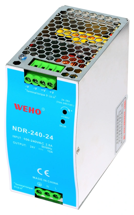
NDR-240-24 configuration reference; EFT results require a matching report and setup.
View original photograph ↗
Ask WEHO which model-specific EFT evidence is available and what assembly, ports, loading, edition, and performance criterion it covers. Give the laboratory the complete cabinet configuration so it can determine the remaining equipment assessment. A supply photograph identifies the proposed hardware; it neither reports an EFT pass nor establishes immunity of the external control cable in the hypothetical example below.
Write observable functional criteria
Translate “no malfunction” into conditions the test team can observe. List the critical functions, their normal states, allowed deviations where permitted by the governing requirements, and how recovery will be assessed. Assign a monitoring method to every important criterion.
Record behavior during exposure as well as after it. An application may resume normally after a reset while having lost a command or interrupted a process. A post-test voltage reading cannot reveal that history. Likewise, the supply rail may remain within its required range while an external interface experiences errors.
| समारोह | Observation to plan | Acceptance question |
|---|---|---|
| Power delivery | Relevant rail behavior at the supply and sensitive load, with the measurement method identified | Did the required power condition remain satisfied? |
| Controller operation | Reset cause, restart count, watchdog indication, and task-state record | Was a restart permitted, and was the required state preserved? |
| Communications during the burst sequence | Exposed cable-port ID, time-correlated retries or missing messages, stale-data interval, and application acknowledgment | Did the interface meet its required continuity during exposure and recovery afterward? |
| Commands and stored data | Output state, settings, counters, and transaction integrity | Was there an unintended action or unacceptable data change? |
These are proposed observation categories, not a replacement for the applicable performance criterion. If that criterion requires uninterrupted operation, an automatically recovering reset is still relevant evidence against the requirement. If temporary degradation is permitted, define its boundaries without retroactively relaxing them after a failure.
Use a correlated event record
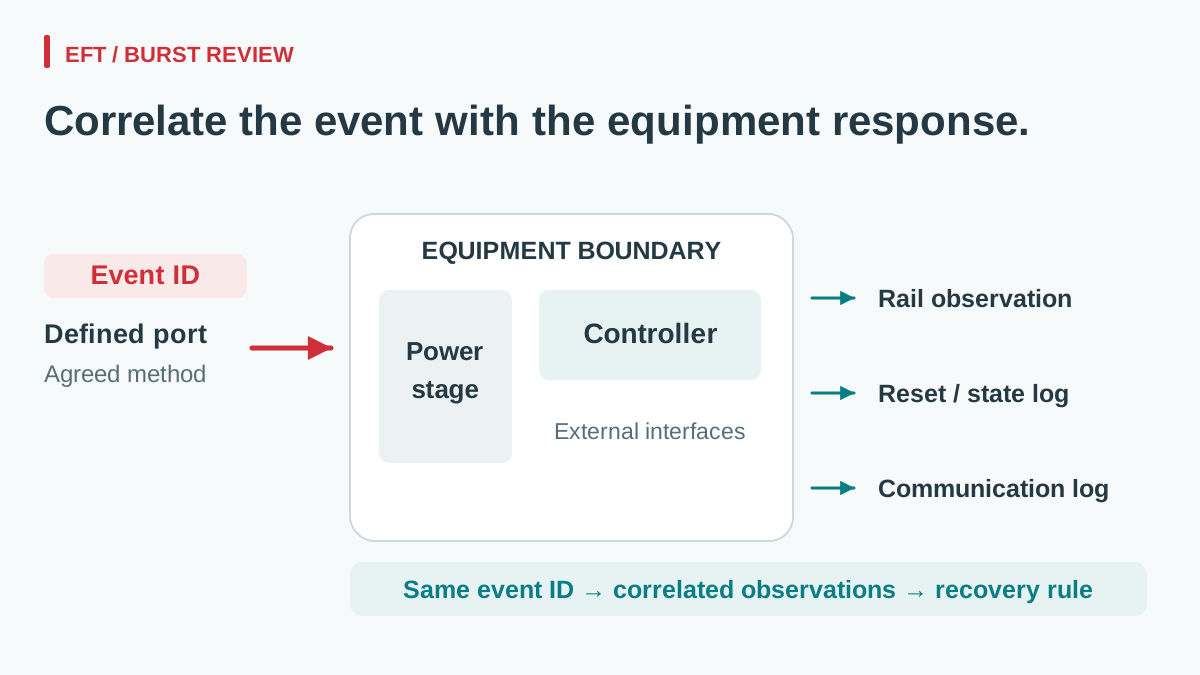
Plan a common timeline linking each exposure to system observations. Identify the test step, port, polarity, program, operating mode, and monitoring channels. Where feasible, retain a time-correlated rail capture, reset or event log, and communication result. State the resolution and limitations of each monitoring method.
Keep monitoring from changing the tested configuration unnecessarily. Probes, instrument grounds, and additional communication leads can affect a system. Have the test team document their arrangement and explain any method used to observe the equipment without introducing an unintended connection.
For baseline electrical measurements, the power-supply ripple acceptance guide helps define measurement conditions. Normal ripple acceptance and EFT immunity remain separate checks; passing either does not establish the other.
Example: a cable-port disturbance leaves stale process data
In a hypothetical machine qualification, an EFT exposure is applied through the agreed coupling arrangement associated with an external control cable. The monitored supply rail stays within the project voltage envelope, but communication retries increase and the controller continues displaying a stale process value. The link returns to normal after the event. A note saying “system recovered” would miss the stale-data interval and the route associated with the exposure.
Compare the stale-data interval, its indication to the operator and any downstream action with the criteria agreed before testing. Retain the specific cable-port ID, coupling arrangement, cable routing, timestamps and protocol logs beside the rail record. Record a nonconformance where a required function was not maintained. An apparently stable rail does not establish that every relevant disturbance path was excluded, and the communication error alone does not identify the AC-DC supply as its cause.
After an engineering change, identify exactly what changed and arrange the necessary repeat assessment. A new filter, cable route, shield connection, or firmware recovery behavior creates a new configuration record. Do not combine its passing outcome with the earlier setup as though nothing changed.
Review supplier evidence and the system report separately
A supplier’s power-supply test report can support candidate selection when the model, revision, ports, load, setup, standard edition, and performance criterion match the claim. It does not automatically cover the OEM’s enclosure, external interfaces, or firmware.
The release record should therefore include the supplier evidence and the equipment-level findings, with their scopes stated. Use the power-supply replacement checklist when a later substitution may affect the qualified assembly.
Send WEHO your power-supply requirement and proposed EFT evidence matrix, including the input source, load, relevant ports, installation, and required functional behavior. Ask which model-specific evidence is available, then agree the remaining equipment-level evaluation with your EMC engineer and laboratory.