For an IT distribution system, verify both the voltage across the supply input and the voltage each input conductor can reach relative to earth, including the defined fault conditions. A wide AC input range alone cannot establish compatibility.
An OEM panel engineer should obtain the installation’s earthing-system description and the supply manufacturer’s permitted conditions before approving the pairing. The WEHO RSP-320-12 family is used to show the document questions. The public information reviewed here does not establish RSP-320-12 approval for IT distribution.
Define the IT system at the equipment connection
IT describes an earthing arrangement, not an information-technology load. Schneider Electric’s IT-system guidance describes an installation insulated from earth or connected through sufficiently high impedance, with exposed conductive parts earthed. It also describes insulation monitoring where an IT system is used for continuity of supply. That explanation provides system context; it does not approve any WEHO supply.
Obtain the actual source drawing from the installation designer. Record whether a neutral is distributed, which two conductors feed the equipment, and how protective earthing and fault monitoring are arranged. “230 V IT” is not enough information to settle the input insulation question.
Keep the installation’s protective strategy under the responsible designer’s control. Changing a power supply must not silently change the earth connection or defeat a monitoring arrangement.
Separate operating input range from voltage-to-earth suitability
The RSP-320-12 page lists an AC input range of 90–264 V. That describes a stated operating input window. The same page includes input-to-frame dielectric-test information, but a test voltage is not an automatic declaration of allowable continuous working voltage to earth, network type or fault-state operation.
Request the manufacturer’s permitted earthing systems and maximum input-conductor-to-earth conditions for the exact supplied construction. Include the intended first-fault conditions and their duration in the request. Do not convert a one-minute insulation test into an unlimited service rating.
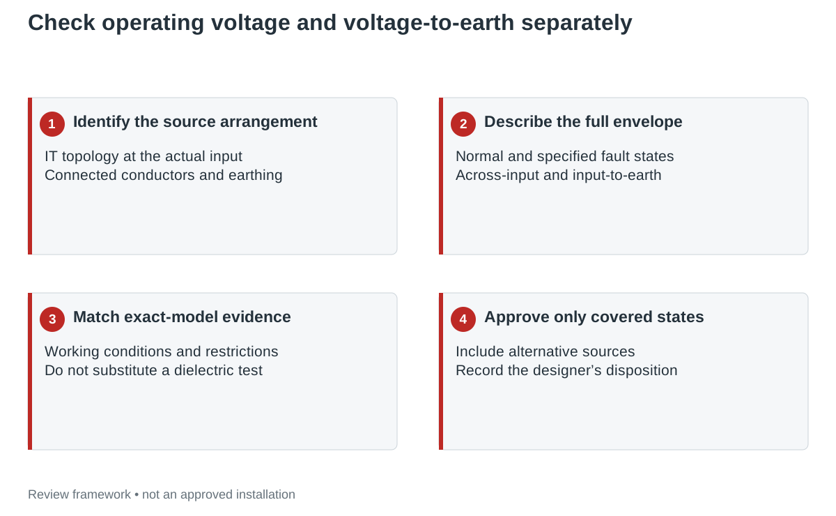
Build a normal-and-fault envelope with the installation designer
| Condition | System information required | Supply evidence required |
|---|---|---|
| Normal operation | Voltage between connected conductors and each conductor to earth; expected variation. | Permitted working conditions for exact model/revision. |
| Specified first earth fault | Which conductor faults, resulting voltage-to-earth envelope and permitted duration. | Suitability for that network and stress envelope. |
| Monitoring operation | Monitoring method, connected network and relevant installed capacitance/leakage limits. | Relevant input/filter characteristics and manufacturer restrictions. |
| Protection and disconnection | Project rules and the responsible designer’s fault-response requirements. | Installation instructions and any required external protection. |
| Source change or bypass | Every source that can feed the input and its earthing arrangement. | Coverage of each allowed source configuration. |
Attach the source document to each numerical entry. Where the installation design has not established a value or state, ask for it; do not let an unfilled cell become an assumed pass.
A correct voltage across the input can leave a separate gap
Illustrative review case: a panel proposal shows the expected AC voltage between its two supply conductors inside the published RSP-320-12 operating range. The equipment drawing labels one conductor N because that is the terminal name on the supply. The site drawing, however, does not establish that the conductor is an earth-referenced neutral under every allowed condition.
The terminal name does not resolve the system topology. Return the proposal for the normal and specified fault-state voltage-to-earth values, then request exact-model confirmation against that envelope. The result may be further documentation, a different approved supply or a system-design change; the input-range comparison alone cannot choose the answer.
Do not use a favorable no-load demonstration as a substitute for this evidence. A supply can appear to operate while questions about insulation stress, monitoring interaction or required protection remain unanswered.
Agree the assessment scope before testing
Have the equipment designer, supply manufacturer and installation designer agree which claims are supported by documents and which need evaluation. A test plan should identify the permitted states, representative sample, monitoring observations and acceptance basis. The test method and fault simulation belong to qualified personnel using the applicable procedures.
Avoid changing internal filter parts, removing protective earth or adding a new bonding link to make a sample appear compatible. Those changes create a different construction and can undermine the installation’s protective design. If a manufacturer specifies a configuration option, retain the exact instructions and its scope.
Include all allowed operating sources in the review. A panel that can also be fed through a UPS or generator needs the relevant source and earthing information for those states. One accepted source configuration does not approve another.
Record the scope of the actual decision
Use the blank IT-system supply evidence matrix to identify the connection, applicable documents and unresolved requests. Record whether the exact pairing is supported, requires further evidence or must be changed. State the approved operating states and revisions rather than writing only “IT compatible.”
For RSP-320-12, keep the public-page reference separate from a project approval. It identifies the family to discuss with WEHO; it does not establish a network qualification absent from the model’s confirmed installation documentation.
Use the project record
Open the blank IT distribution system and power-supply evidence matrix to record your conditions, evidence and decisions. The worksheet contains no pre-approved result.
Request an assessment against your actual network
Send WEHO the RSP-320-12 variant, site earthing-system drawing, connected input conductors, normal and fault-state voltage-to-earth envelope, monitoring arrangement and intended operating sources. Request exact-model installation suitability and any limits for that configuration.