



Key Engineering Takeaways
- Several LED branches on one source share a service dependency even when their normal load total is acceptable.
- State which other branches must remain lit when one branch is removed, disabled or develops a defined fault.
- XLG-75-24 documentation lists 24 V and 3 A; it does not establish independently isolated branch outputs.
- Separate an open-branch service check from a controlled fault-response test and record the unaffected branches.
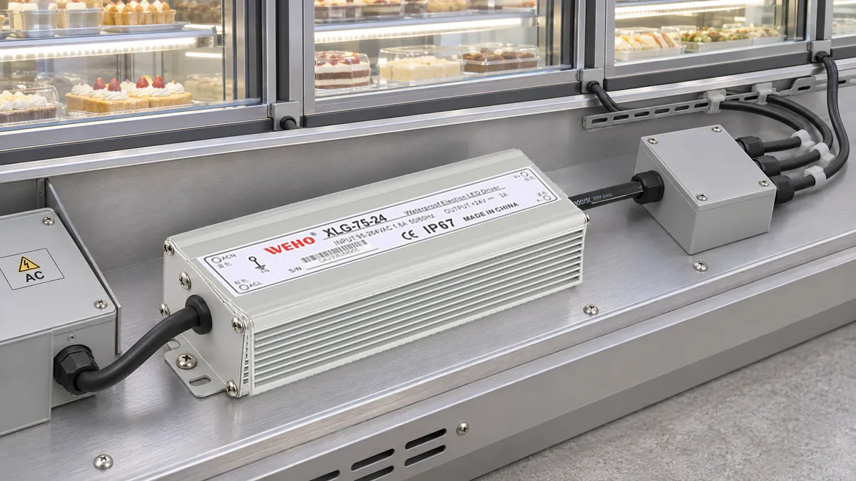
A Single Branch Event Can Become a Whole-Zone Interruption
A lighting assembly may contain several separately labeled LED branches powered by one driver. That arrangement can be practical, but a branch label does not mean the branches have independent power availability. The shared source, return path or distribution device can create a common interruption.
The WEHO XLG-75-24 driver is an identity reference for this architecture review. The buyer's decision is whether the proposed system meets its continuity requirement when one branch changes state. This is a system-level question that cannot be answered by the driver's wattage class or protection-mode name alone.
Define What Must Continue Working
Start with the equipment's operating requirement. Does the project permit the entire lighting zone to go dark while a branch is serviced? Must the remaining branches stay above a specified light level? Is an operator-visible alarm required, and who defines its timing?
Write those outcomes before planning a test. “Other branches are unaffected” is too broad unless the relevant voltage, light output, interruption duration or controller behavior has been defined. Choose the measurements that matter to the actual task instead of assuming that any visible light counts as acceptable operation.
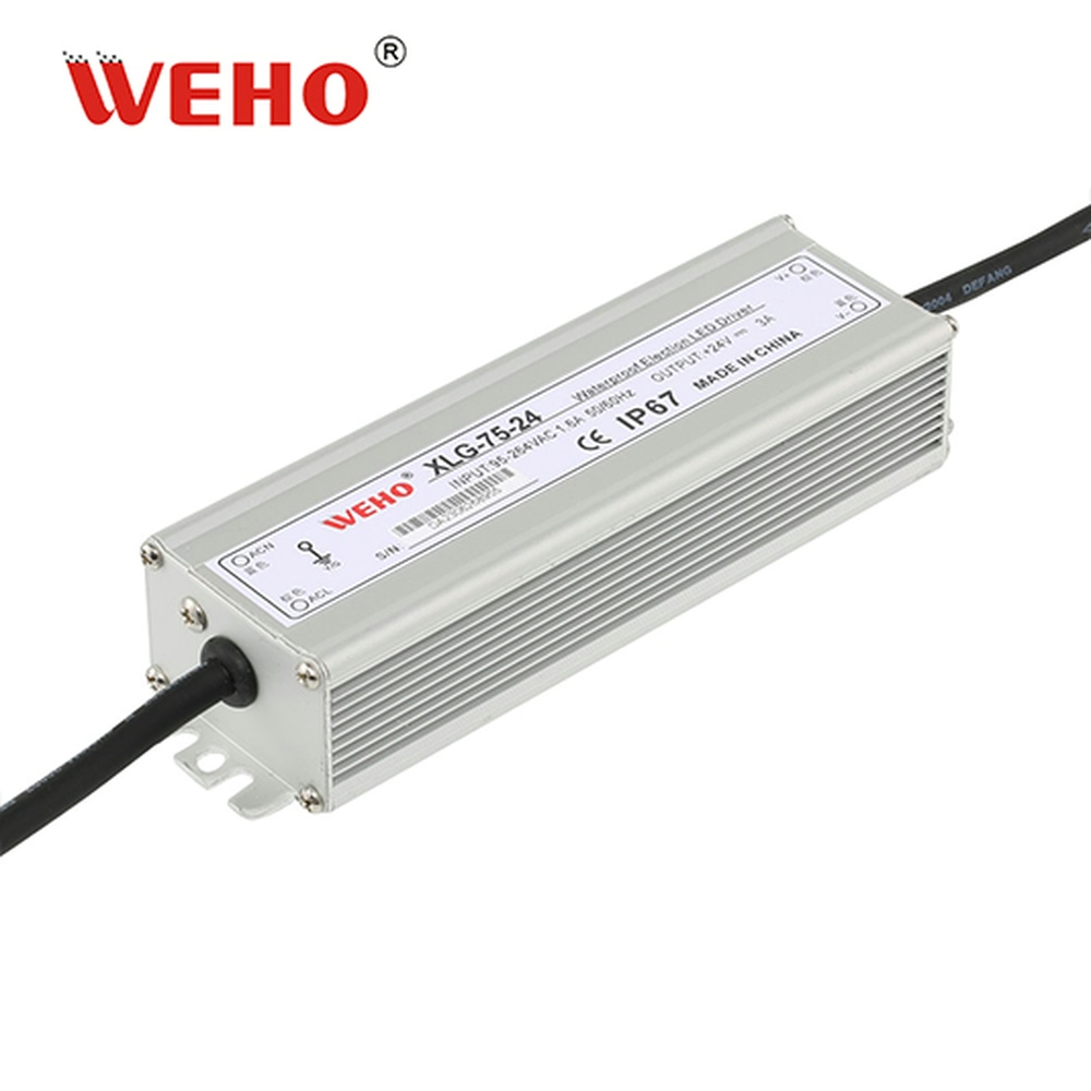
The XLG-75 manufacturer specification lists 24 V and 3 A for this variant. Their nominal product is 72 W. Neither that arithmetic nor multiple visible cable entries establishes separate current-limited or isolated channels for the individual project branches.
Keep the manufacturer's product boundary distinct from the OEM distribution design. External branch protection, switching devices and return paths need their own circuit records. An overcurrent-protection description for the source does not prove that an external branch protective device will operate selectively.
| Project event | Question for other branches | Evidence to record | Do not assume |
|---|---|---|---|
| Branch commanded off | Do remaining loads keep their required state? | Commands, shared-bus voltage and output observations | Commanded off means physically isolated |
| Branch opened for permitted service | Does the service path interrupt another branch? | Actual circuit boundary and branch observations | A separate label means an independent return |
| Defined branch fault | Which branches lose required operation? | Approved fault condition and time-based response | Source protection gives branch selectivity |
| Fault removal and restart | Do the correct branches recover in the required state? | Recovery order and retained controller state | Automatic source recovery means acceptable system recovery |
Build the Branch Map Before the Current Sum
Draw the actual source, distribution points, branch loads and return connections. Mark common components explicitly, including a shared connector, common switch or return conductor. A drawing with several lines leaving one box does not establish that each line has an independent failure boundary.
Identify control and data connections as well as the power conductors. A controller may continue to command a branch while its main power path is absent, and a common control action may intentionally turn several branches off together. Record those relationships rather than interpreting every simultaneous interruption as a driver fault.
The service boundary also needs a clear meaning. A planned, de-energized disconnection under the equipment procedure is different from opening a connector while it carries current. This article does not establish hot-plug capability for the driver, LEDs or project connectors.
Use a Load Example Without Claiming Fault Independence
Consider a hypothetical three-branch assembly with steady currents of 0.70 A, 0.80 A and 0.50 A at 24 V. The sum is 0.70 + 0.80 + 0.50 = 2.00 A, giving 24 × 2.00 = 48 W at the assumed operating point.
That sum is below the published 3 A nominal figure. It does not establish allowable loading under every temperature or input condition, and it does not prove continuity during a branch fault. Startup behavior, the actual LED loads and the installed thermal conditions still require their applicable checks.
If branch A is opened under the approved service arrangement, the remaining assumed steady current is 0.80 + 0.50 = 1.30 A. A useful service check asks whether branches B and C retain their required operation in that configuration. It does not infer the answer from the lower current sum.
A low-impedance fault is a different event. Depending on the system and protection design, it can disturb the shared bus before, during or after protective action. The project must establish the actual response through a controlled plan; do not substitute the benign open-branch result for fault-continuity evidence.
| Hypothetical state | Normal current calculation | Continuity requirement | Result field |
|---|---|---|---|
| A, B and C enabled | 0.70 + 0.80 + 0.50 = 2.00 A | All required lighting states available | Record actual operation and bus voltage |
| A opened through permitted service procedure | B + C = 1.30 A assumed | B and C retain their defined required output | Record interruptions, if any |
| Approved defined fault on A | Not predicted by steady load addition | Outcome set by the equipment requirement | Record every branch and protection response |
| Fault cleared | Returns to the applicable commanded load | Correct recovery without unintended state changes | Record restart order and observations |
No row in this example is an observed XLG-75-24 result. The current arithmetic explains the normal operating states; the empty result fields preserve the difference between a design assumption and verified continuity.

Swipe horizontally on a small screen, or open the full-size diagram.
Plan a Bounded Service and Fault Verification
- Freeze the architecture. Record the source revision, all branch and return paths, external protection and control relationships. Changes to shared components can change the interruption boundary even when the driver is unchanged.
- Approve the required outcomes. Define the other branches' permitted interruption and output behavior. Use requirements from the equipment owner or design authority rather than a generic no-flicker promise.
- Perform the permitted open-branch check. Use the equipment's approved de-energized service arrangement and record the resulting state after restoration. Verify that the intended branch boundary was actually opened.
- Treat faults as a separate test scope. Qualified personnel should use an appropriate controlled test arrangement and approved fault conditions. Do not create an improvised short circuit in an installed lighting system to discover its behavior.
- Observe all relevant branches. Record bus voltage, the affected branch and the branches expected to continue. A single current trace from the source cannot prove that each remaining receiver stayed functional.
- Check recovery. Record what occurs after the permitted fault removal or service restoration. Note whether a controller must restart, a command is retained or a deliberate re-enable is required.
Download the shared-branch continuity worksheet to separate the event, expected outcome and observation. Include the circuit revision so that later wiring changes do not inherit an earlier result without review.
If the question is how to define a source fault test itself, use the separate power-supply short-circuit test record. The additional acceptance question here is what the other lighting branches experience, not whether the source eventually restores its own output.
Choose an Architecture Against the Required Service Boundary
A project that requires independent service continuity should identify the common items that can defeat it. The solution may involve a different distribution arrangement, suitably coordinated external protection or separate source domains. The correct choice depends on the complete equipment design; the current sum does not choose it automatically.
Do not claim independence from two separately routed cable pairs if both ultimately share an unverified source or return path. Conversely, do not assume that every branch event must interrupt the whole assembly. The map and bounded test determine which behavior has actually been established.
For an XLG-75-24 system review, send the branch map, steady and startup loads, required continuity, proposed protective devices and relevant operating conditions. Ask for applicable product information while keeping the system's branch-continuity verification with the equipment design record.
Engineering FAQ
Do three LED branches mean the driver has three independent outputs?
No. Project branches can share a single source and common return. Independent or isolated outputs require explicit documentation for the exact product and circuit; cable count or labels do not establish them.
Does a 2 A normal load prove that a 3 A source will preserve every other branch during a fault?
No. Normal current addition does not predict the shared-bus and protection response to a fault. Verify that response against the project's actual continuity requirement using a controlled test plan.
Is opening a branch the same as testing a short circuit?
No. An open branch removes its normal current path, while a low-impedance fault imposes a different condition on the source and distribution. Record them as separate events with separate expected outcomes.
Does automatic recovery prove that the lighting system passed?
No. The source may recover while a receiver restarts incorrectly or another required branch experiences an unacceptable interruption. Acceptance must include the relevant branch behavior and the complete system's required recovery state.



