A dual-output switching power supply needs a recorded reference for each output, not just two voltage entries. Before releasing the BOM, identify the exact AC-input model, the terminals between which each voltage is specified, and the receiving circuit connected to those nodes. Record whether the returns are common or separate from an applicable manufacturer drawing.
On this page
This is a purchasing and engineering handoff for equipment with two DC rails. It prevents a substitute with familiar voltage numbers from changing the circuit reference, connector assignment or approved assembly without review.
Start with the actual D-60B specimen
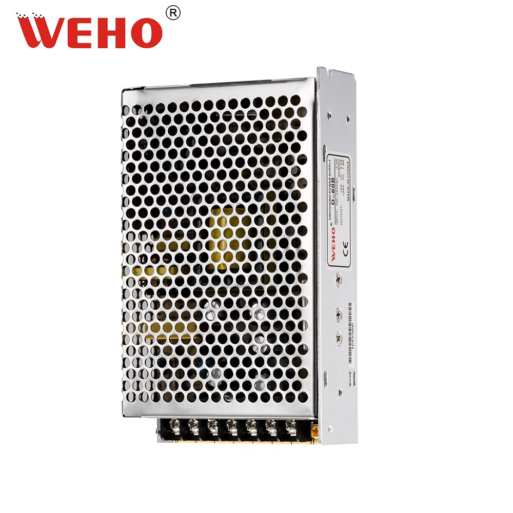
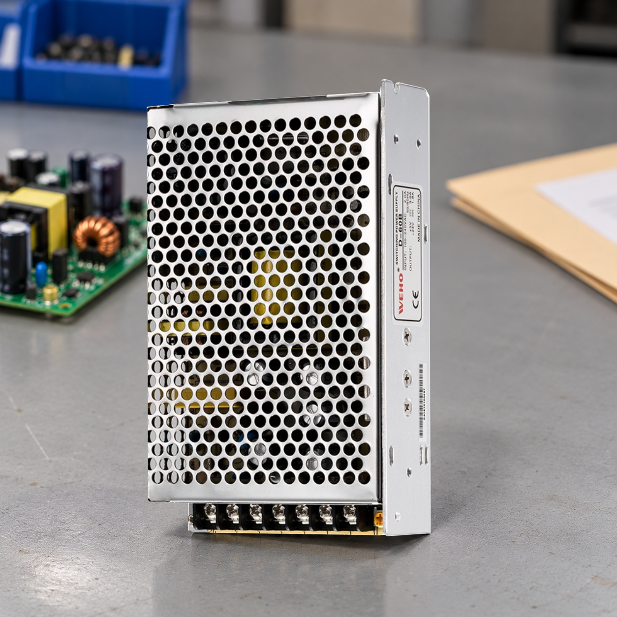
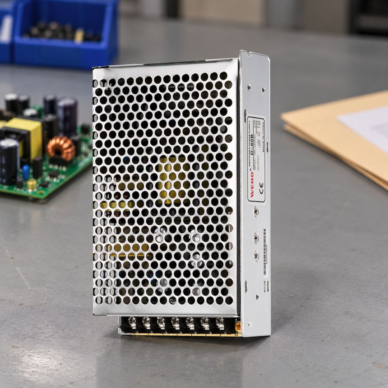
The pictured WEHO specimen is labeled D-60B, with 5 V and 24 V output markings. The individual D-60 dual-output AC-DC product page includes this variant. The full suffix belongs in the BOM: a family name or a supplier description such as “dual 60 W” is insufficient identification.
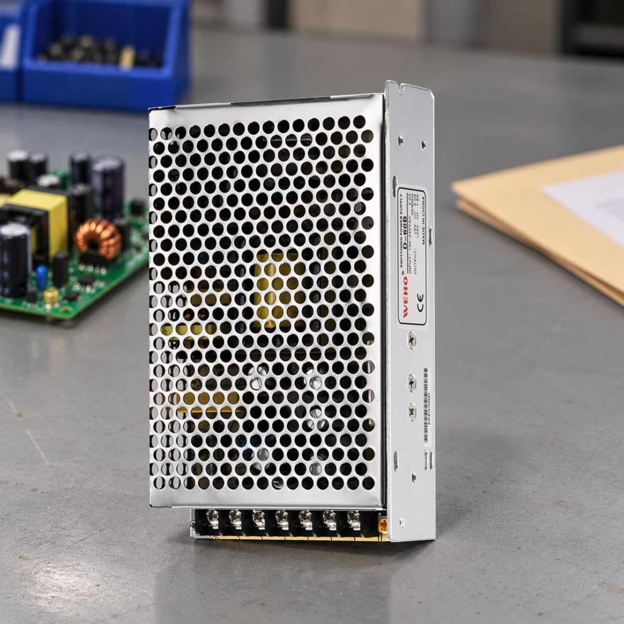
Keep this specimen photograph with the applicable output table and terminal drawing. The public family table and photographed label differ in their D-60B current entries; obtain the revision that applies to the ordered unit instead of carrying either set into the BOM by default. This view does not show the complete terminal/reference information needed to release a wiring schedule. Obtain that drawing and transcribe its terminal names exactly. Do not turn a guessed COM connection into a production instruction.
Make the return reference an explicit BOM field
“Two outputs” counts rails; it does not establish their relationship. For every rail, write the voltage as a measurement between two named nodes. If a documented COM serves both rails, map each receiver return to that node. If the manufacturer specifies separate output circuits, preserve that distinction until the complete equipment interconnection has been reviewed.
Input-to-output insulation, output-to-output separation and protective earth are different record fields. Neither the perforated metal cover nor the number of screws answers those questions. A pairwise insulation statement must identify the terminals it covers. For an output-to-earth proposal, use a separate protective-measure and interface review; a common return does not itself settle that system-level decision.
| BOM attachment field | Entry to retain | Release check |
|---|---|---|
| Supply identity | D-60B, manufacturer and controlled document revision | PO, delivered label and accepted sample agree |
| Available source | Actual AC voltage/frequency range and connection drawing | Supply input version matches the installation |
| Rail A / rail B | Specified voltage, return terminal and applicable current limits | Each receiver is assigned to the correct voltage pair |
| Reference relationship | Documented common or separate returns; source drawing reference | No undocumented jumper or assumed output isolation |
| Receiver interface | Connector cavity, pin name, polarity and drawing revision | Source terminal maps to the actual receiving pin |
| Acceptance baseline | Sample identifier, photograph, checks and approving owner | Delivered configuration can be compared with an approved record |
Use a voltage-pair worksheet before a wiring drawing
Hypothetical example: an interface requires a 5 V rail at 2 A and a 24 V rail at 0.5 A. Its steady DC demand is (5 × 2) + (24 × 0.5) = 22 W. That arithmetic describes the assumed load; it is not a D-60B rating, simultaneous-output limit or selection approval.
Now add the reference. The receiver specifies both voltages relative to connector pin C0. The supplier drawing must establish which output return, if any, may connect to C0. Write V(A, C0) and V(B, C0) in the interface record. “5 V + 24 V” alone cannot answer the connection question.
Preserve the drawing view and revision with that worksheet. A terminal count or a continuity observation on an unidentified bench sample cannot replace the supplier’s connection definition. If the source drawing changes, reopen the receiver-reference check before the new batch is wired.
Keep the load worksheet separate from the terminal schedule. A correct 22 W sum does not establish individual rail capacity, combined-rating restrictions, allowable return current or loading conditions. Link those checks to the exact output table rather than accepting the series number as a usable-power result.
Control a change in output count or reference
The separately identified Q-60 product carries the specimen identifier Q-60B. Its additional outputs make it a different interface candidate, not an automatic D-60B replacement. Keep its output map in a separate record; unused rails, shared references and receiver connections still need explicit disposition. The next electrical check is a four-rail load and acceptance matrix for the proposed configuration.
For a proposed substitute, mark each BOM field as unchanged, changed or unresolved. A new connector assignment requires an updated harness drawing. A changed reference relationship requires an electrical interface review. A different output table requires a revised load check. Purchasing should release the new order only after the responsible engineer closes the affected fields.
Hand over one linked baseline
Send WEHO the two receiver voltage pairs, required currents, available AC source and proposed return connections. Request the exact D-60B output/terminal documents and an acknowledgement tied to the ordered suffix. Retain the accepted specimen photograph alongside that acknowledgement.
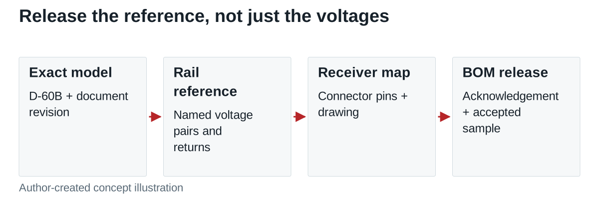
The useful deliverable is one linked baseline: ordered model → source drawing → rail/reference map → receiver connector → accepted sample. Service staff can then replace the supply by checking that record, and a later BOM change cannot silently alter the equipment’s DC reference.