



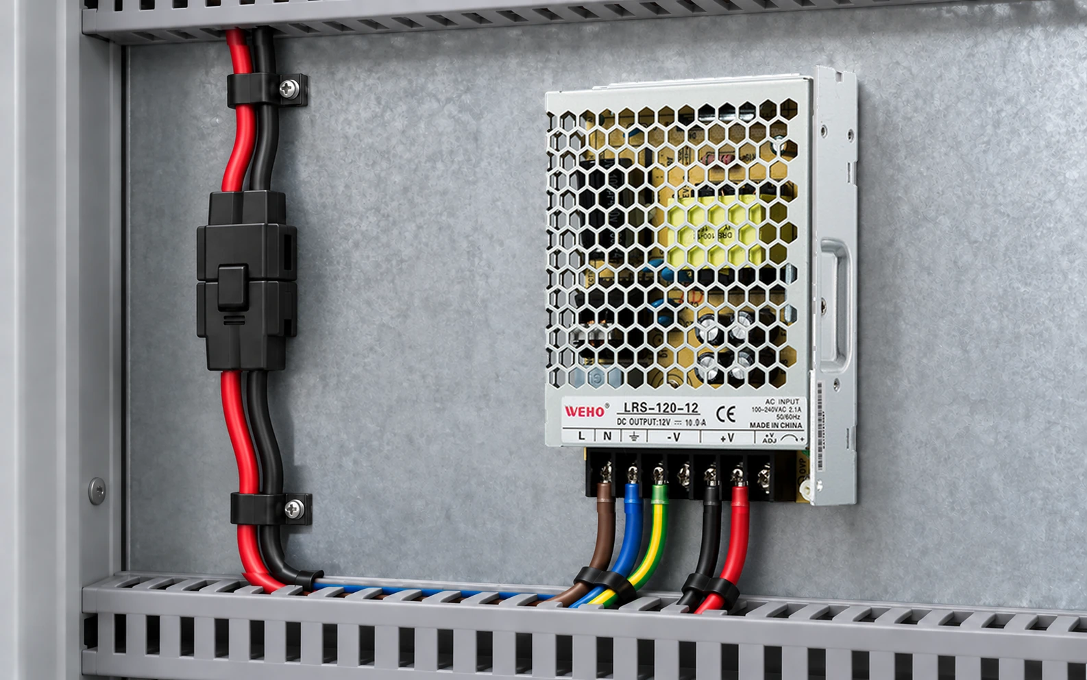
A connector’s continuous-current rating does not establish that it may be connected or separated while a 12 V load is energized. For a serviceable DC assembly, specify the intended mating state and obtain the connector’s applicable operating permission before approving the interface.
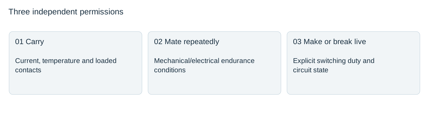
This guide helps a machine OEM review a detachable receiver powered by an LRS-120-12. It distinguishes three questions: can the connector carry the current, can it survive the planned mating cycles, and can it make or break this live circuit?
Separate carrying current, mating endurance and switching duty
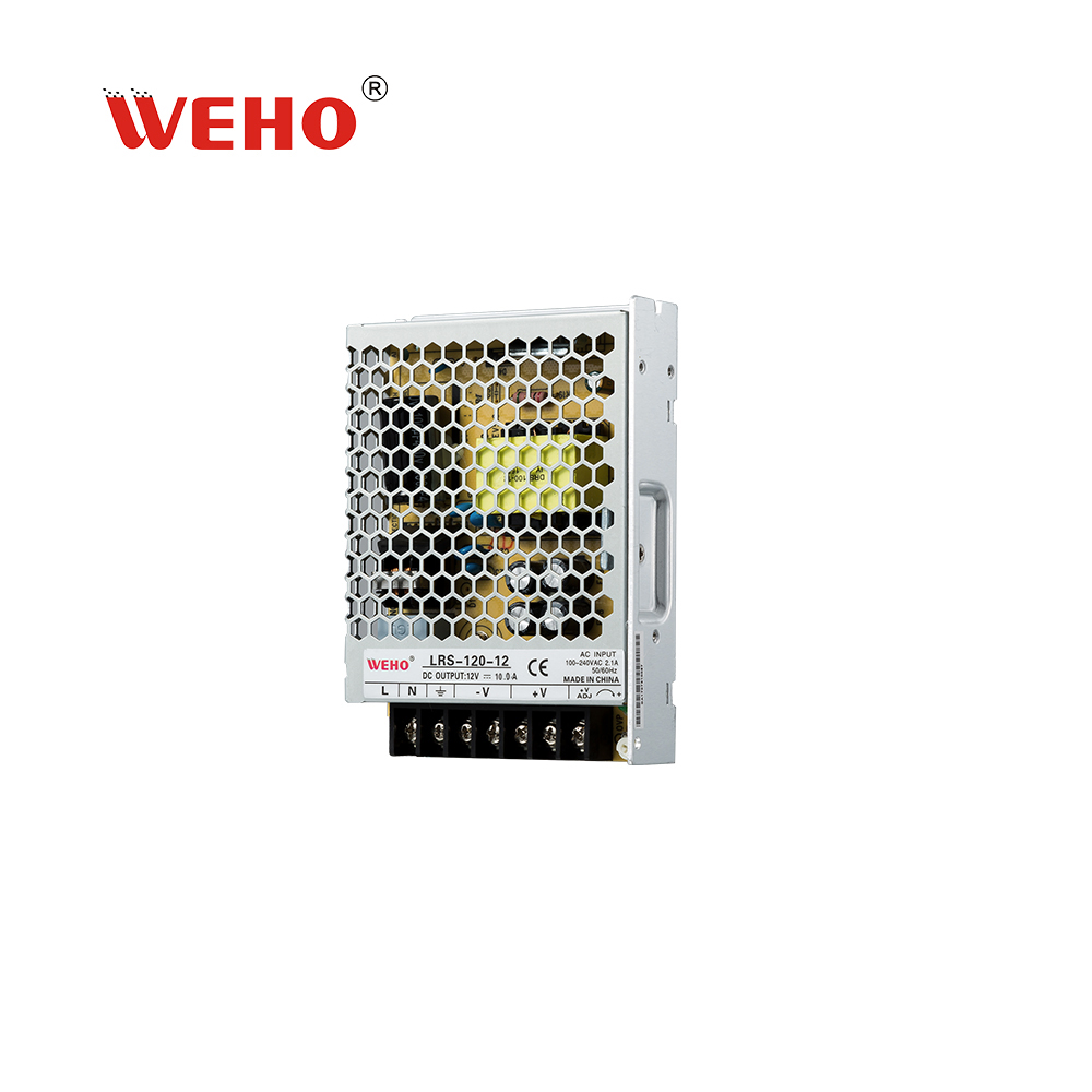
IL WEHO LRS-120 table lists the 12 V version at 0–10 A. That is not a rating for an external plug. A connector selected for the branch needs its own evidence at the intended conductor, contact loading, ambient temperature and mating combination.
Mechanical endurance in mating cycles describes a separate duty. It does not automatically include electrical making or breaking under the receiver’s load. The mating pair, contact finish and test conditions must match the proposed use.
Phoenix Contact, for example, explicitly states that a cited COMBICON connector has no switching power and must not be mated or separated live or under load in its intended use. This is evidence that permissions are connector-specific, not a restriction or approval automatically assigned to every connector.
Describe the service state at both halves of the connector
Write the procedure in terms of actual circuit states. “Power off” may mean a software command, removal of an upstream input, opening a DC switch or verified isolation of all relevant sources. These are different actions. A receiver with stored energy or a second communication-powered source can leave voltage on a supposedly disconnected interface.
Trace positive, return, PE or chassis connection where applicable, and every auxiliary signal. Identify which half can remain energized after separation. Do not assume that a recessed socket eliminates the requirement to assess accessibility or that a low nominal voltage makes any procedure acceptable.

Describe the load encountered at connection and separation
| Moment | Question | Useful evidence |
|---|---|---|
| Initial connection | Does an input capacitor produce a charging event? | Receiver inrush or approved connection test |
| Normal operation | How many contacts carry current simultaneously? | Loaded-contact and ambient conditions |
| Separation | Is current already interrupted by an approved means? | Circuit state and connector instructions |
| After separation | Can either half retain or receive voltage? | Stored energy and alternate-source review |
A 6 A steady load, for example, may pass a hypothetical 8 A continuous-current screen under the connector’s stated conditions. It has not thereby passed a live-disconnection assessment. Do not calculate a universal allowable break current by subtracting running amperes from the connector’s carrying rating.
Choose a service concept supported by the connector documents
One concept uses a connector only after the documented de-energizing and verification sequence. Another requires a connector and circuit explicitly designed and rated for the intended switching duty. The engineer must evaluate the actual equipment and applicable requirements before choosing.
For energized connection, ask for the complete permission: DC voltage, current, load type, make/break sequence, cycle count, mating pair and environmental conditions. A marketing phrase such as “quick disconnect” is not that evidence. Likewise, a protective cover or color key does not create an electrical switching rating.
Keep service instructions aligned with the released hardware
Put the connector part numbers, pin assignment, permitted mating state and verification sequence on the same released interface drawing. Use identification that prevents a similar plug from being substituted silently. Ensure the actual technician can follow the procedure without guessing which source has been disabled.
After a cable, receiver board or connector change, review the affected carrying, endurance and switching conditions again. A clear service-state record is more useful than a generic statement that the connector is rated above the supply current.
For a service connector on an LRS-120-12 assembly, provide its exact part number, mating pair, conductor size, load current and intended disconnect state. Request the applicable supply connection instructions and obtain the connector manufacturer’s separate evidence for any proposed energized mating or breaking duty.
Detachable DC interface release record
| Interface conductor | Source after shutdown | Relevant connector permission | Verification | Proprietario |
|---|---|---|---|---|
Blank project worksheet. Enter verified project data; example calculations above are not measurements.



