



- Power supply screw selection must satisfy maximum intrusion and minimum engagement at the same time.
- Calculate the longest screw against the thinnest external stack; check the shortest screw against the thickest stack.
- Use the ordered model’s controlled mounting drawing to establish limits. An M3 thread callout alone is insufficient.
- The worked dimensions below are hypothetical assembly inputs, not approved WEHO screw lengths.
Why a screw that fits can still fail the assembly review
A mounting screw can tighten normally yet project too far inside a power supply. A shorter replacement may avoid intrusion but leave inadequate thread engagement. The release decision therefore concerns a complete fastening stack, including dimensional tolerances and the chosen fixing face.
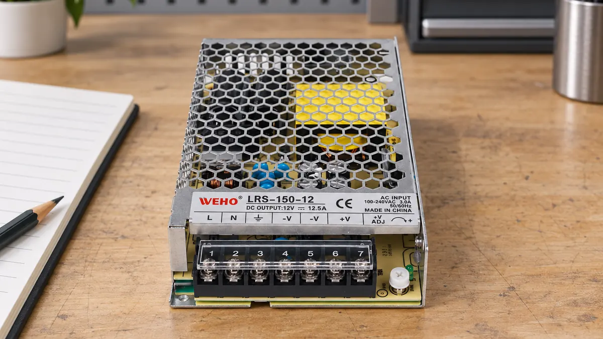
For an OEM using the LRS-150-12 mechanical product reference, keep the ordered revision with its mounting drawing. This article develops the screw-length check; the separate mounting drawing fabrication review covers locating the holes and selecting their reference face.
Define the measurement plane before calculating
Intrusion is the distance a screw extends beyond the power supply's external mounting surface. Screw length is measured from the bearing surface appropriate to its head style. A countersunk screw needs a different geometric interpretation from a screw whose head bears on a flat washer.
Name the reference planes on the assembly drawing. Otherwise, one engineer may subtract the backplate while another also subtracts a chassis wall already included in the supplier's depth definition. Both calculations can look reasonable and still describe different distances.
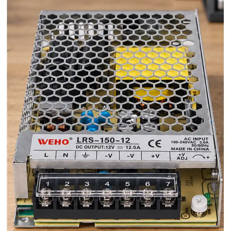
The public WEHO LRS-150 specification includes mechanical views and more than one M3 fixing callout. It does not justify transferring a depth from one face to another, nor treating a drawing annotation as a universal limit for every enclosure revision. Obtain an unambiguous interpretation for the actual mounting interface before production release.
The general risk is established independently: MEAN WELL's installation precautions warn that excessive mounting screw length can contact internal components. Those precautions explain the engineering concern; they do not specify a WEHO screw length or torque.
Separate usable thread from empty space
A maximum intrusion allowance and a minimum engagement requirement answer different questions. Empty clearance beyond a threaded boss may permit a screw tip to enter without providing additional thread engagement. Conversely, a blind thread may limit penetration before any nearby component does.
Request the usable thread interval, allowable penetration, fixing-face definition and permitted fastener details together. Do not derive minimum engagement from thread diameter alone, or assume that the entire calculated projection is useful thread. Material, thread formation and loading affect the fastening decision.
Work a hypothetical tolerance stack
Consider a simplified assembly in which the screw head bears flat on the washer and the threaded interface begins exactly at the power supply mounting plane. This is a hypothetical example with no recess, standoff or unthreaded lead-in. Assume the assembly authority has specified at least 2.0 mm usable engagement and at most 4.0 mm intrusion for this example only.
The proposed screw is 6.0 ± 0.2 mm long, measured under its head. The backplate is 2.0 ± 0.1 mm thick and the washer is 0.8 ± 0.1 mm thick. The washer dimensions represent its assembled bearing thickness; a compressible washer would require its actual loaded range.
For this simplified geometry, projection p equals screw length L minus external stack thickness t. The two limiting checks are:
pmax = Lmax − tmin
pmin = Lmin − tmax
The thinnest stack is 1.9 + 0.7 = 2.6 mm. The thickest stack is 2.1 + 0.9 = 3.0 mm. Therefore maximum projection is 6.2 − 2.6 = 3.6 mm, while minimum projection is 5.8 − 3.0 = 2.8 mm.
Both results fall within the assumed 2.0–4.0 mm window. The upper margin is 0.4 mm and the lower margin is 0.8 mm. These are dimensional margins in the example; they do not establish vibration retention, clamp force, electrical clearance or a production acceptance rule for LRS-150-12.
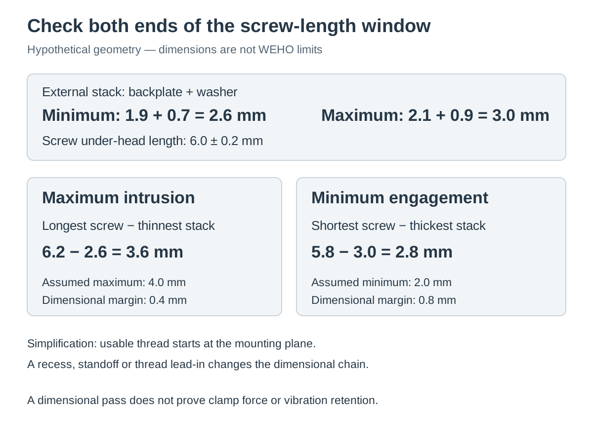
Swipe horizontally on a small screen, or open the full-size diagram.
Compare changes against both limits
The same assembly can fail after a seemingly minor purchasing substitution. An 8.0 ± 0.2 mm screw gives 8.2 − 2.6 = 5.6 mm maximum projection. A 4.0 ± 0.2 mm screw gives 3.8 − 3.0 = 0.8 mm minimum projection.
| Screw length | Projection range | Assumed requirement | Dimensional decision |
|---|---|---|---|
| 4.0 ± 0.2 mm | 0.8–1.6 mm | 2.0 mm minimum | Insufficient engagement in this simplified geometry |
| 6.0 ± 0.2 mm | 2.8–3.6 mm | 2.0–4.0 mm window | Passes the stated dimensional checks only |
| 8.0 ± 0.2 mm | 4.8–5.6 mm | 4.0 mm maximum | Excessive intrusion |
A nominal-only check would report 3.2 mm for the 6 mm screw and conceal the 0.4 mm upper margin. Worst-case arithmetic makes that exposure visible. It also helps purchasing identify which dimensions must remain controlled when a washer, bracket or screw supplier changes.
Add omitted geometry explicitly
If the first usable thread starts inside the mounting plane, subtract that setback when checking engagement. If a spacer separates the enclosure from the plate, add its loaded thickness to the external stack. Track these distances as signed dimensions with a small section sketch.
Do not apply the simplified projection formula unchanged to a recessed or countersunk assembly. Update the actual bearing plane, thread interval and dimensional chain, then recompute the extremes. A section drawing is more useful than a photograph for resolving those interfaces.
Release the fastening system, not one catalog number
A screw-length calculation is only one part of the mounting record. The assembly also needs an approved fastener material, head form, washer arrangement, tightening procedure and retention method. Reaching a torque setting does not prove that a screw is clamping the stack rather than bottoming out.
| Il record | Owner or source | Check that closes the decision |
|---|---|---|
| Mounting face and depth definition | Applicable supplier drawing | Reference planes and hole identifiers agree |
| Length and stack tolerances | Fastener and fabrication drawings | Both worst-case projections satisfy the approved limits |
| Usable thread and engagement | Supplier interface requirements | Actual overlap meets the specified engagement requirement |
| Tightening and retention | Approved assembly procedure | Installed sample matches the documented method |
| Service replacement parts | Released BOM | Maintenance substitutes preserve the complete stack |
Verify the assembly before freezing the BOM
- Identify the interface. Record the exact model, ordered revision, fixing face and hole identifiers. Verify that the controlled drawing describes the supplied unit rather than a visually similar family member.
- Build the dimensional chain. Record screw length, loaded stack thickness, recesses and usable thread coordinates. Verify the measurement planes on a section drawing before calculating.
- Calculate both extremes. Record maximum intrusion and minimum usable engagement with their limiting combinations. Accept only against applicable documented limits; obtain missing limits before releasing the fastener.
- Check an isolated sample assembly. Record the selected parts and inspection method under the equipment's energy-isolation procedure. Verify seating and absence of bottoming without opening or probing an energized supply.
- Control substitutions. Record the complete stack in the BOM and service instructions. Recalculate whenever a change can alter bearing geometry, thread overlap or clamping conditions.
Prepare a mechanical question for WEHO
Use the LRS-150-12 mounting reference page with your assembly section, proposed fastener and tolerance calculation. Send WEHO the model and fixing-face question and ask for the applicable controlled drawing, intrusion interpretation and fastening requirements before approving production hardware.
Frequently asked questions
Does an M3 marking tell me the allowed screw length?
No. M3 identifies a nominal thread size, while allowable intrusion and required engagement depend on the actual interface. Obtain the fixing-face limits and measurement definitions for the ordered revision.
Can adding a washer make an overlong screw acceptable?
A washer can reduce projection, but it does not automatically make the fastening system acceptable. Recalculate with its assembled thickness and tolerances, then verify bearing, retention and the approved washer arrangement.
Is more thread engagement always better?
No. Additional projection can exceed the permitted intrusion or reach a blind-hole bottom. Engagement must meet its documented minimum while penetration remains within the allowed envelope.
Can the nominal screw calculation replace a sample inspection?
No. The tolerance calculation and sample inspection address different errors. Arithmetic checks the specified dimensional extremes; inspection checks whether the actual parts, bearing surfaces and assembly method match that specification.



