A constant-power electronic load increases its requested current as its input voltage falls. That behavior can interact with a DC-DC source and the test wiring, so a collapse during a bench test does not identify the converter as the sole cause.
- Define the load mode, power setting and operating limits before testing.
- Compare constant-power behavior with controlled current steps where appropriate.
- Check source, load and wiring conditions on the same time reference.
Why is a constant-power load different from a resistor?
A constant-power load tries to maintain P by drawing I = P/V. As voltage falls, its requested current rises. A resistor instead draws less current as voltage falls, provided its resistance stays unchanged. The two loads can therefore produce different behavior on the same source.
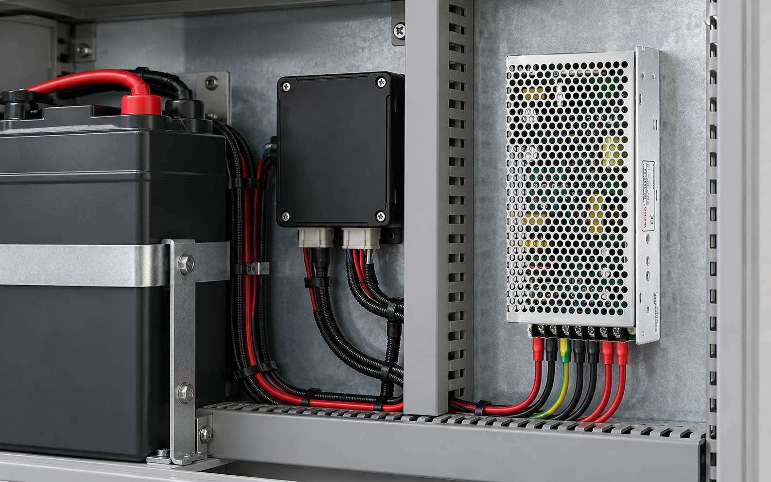
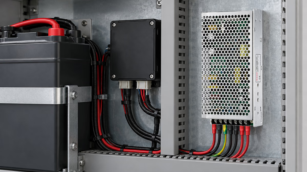
For an OEM assessing an SD-100 DC-DC supply assembly, identify the actual input/output variant before setting test conditions. The family photograph does not establish the allowable input range or dynamic behavior of every suffix. Use the applicable variant documentation for those limits.
An electronic load also has minimum operating voltage, current, power, slew and control-bandwidth constraints. Reaching one of those limits may change how closely it follows the commanded mode. A programmed power value is not proof that the actual load delivered that exact profile throughout an event.
The aim is to determine whether the proposed source-load combination meets a defined project requirement. A test that creates an interaction absent from the intended equipment can still be diagnostically useful, but its relevance must be explained. Avoid translating an unexplained bench oscillation directly into a supplier-quality conclusion.
What does a simple current calculation reveal?
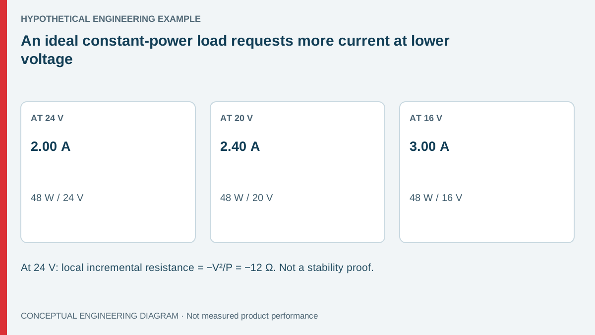
Consider a hypothetical 48 W constant-power load. At 24 V it requests 2.00 A; at 20 V it requests 2.40 A; at 16 V it requests 3.00 A. These are arithmetic examples, not permitted operating points or performance claims for an SD-100 variant.
The incremental slope is dI/dV = −P/V². Around 24 V and 48 W, the incremental resistance dV/dI is −V²/P = −12 Ω. This describes a local change under an ideal constant-power assumption; it is not a physical negative resistor that can be selected independently of the load controller.
If the supply or distribution path cannot provide the rising current demand, voltage may fall further. Whether the system actually collapses or oscillates depends on source impedance, control loops, capacitance, load dynamics and limits. The static arithmetic identifies a concern; it does not calculate stability margins.
Do not use the 48 W example as a universal safe test level. A source's available output depends on its actual rating and conditions, while the load may impose startup or transient demands beyond its average setting. The entire test envelope needs a documented basis.
| Example load voltage | Requested power | Ideal requested current | Interpretation |
|---|---|---|---|
| 24 V | 48 W | 2.00 A | Initial arithmetic operating point |
| 20 V | 48 W | 2.40 A | Lower voltage requests more current |
| 16 V | 48 W | 3.00 A | Source and load limits must be checked |
| Below load operating range | Programmed value remains 48 W | Not guaranteed to equal P/V | Record actual behavior and mode status |
Which setup details should be checked first?
Record the electronic load model, mode, setting, slew configuration and voltage/current/power operating region. Check the exact manual for how the load behaves near undervoltage and current limits. Some settings can delay turn-on or change recovery behavior, which matters when comparing two tests.
For primary operating guidance, Keysight's EL30000 electronic-load user guide distinguishes the available regulation modes and their settings. Follow the manual for the actual instrument used; another model's behavior must not be assumed.
Measure at both ends of the distribution path where the diagnostic question requires it. A remote-sense connection, if supported and correctly applied, changes which voltage the load controller sees. Lead inductance and resistance remain part of the physical system even when a display compensates a voltage drop.
Also record the upstream DC source feeding the converter. Its current limit, cable drop or protection response can affect the converter input during the event. A bench arrangement with two regulated devices and a regulated electronic load has several interacting control loops, not merely one converter and an ideal resistor.
How should a controlled diagnostic sequence proceed?
Start inside the documented operating envelope with a suitable low-stress condition. Increase loading according to a planned sequence while observing actual input and output behavior. The sequence should distinguish static loading, startup and load-step questions rather than mixing them into one unexplained failure.
- Confirm the ordered converter variant and relevant input/output limits.
- Verify the upstream source's behavior under the intended demand.
- Establish a stable constant-current comparison point where appropriate.
- Repeat with the defined constant-power setting and capture actual waveforms.
- Change one setup variable at a time and record whether the response changes.
Qualified personnel should arrange energy isolation, suitable probes and guarded connections. Do not add an arbitrary output capacitor or damping network to suppress a waveform without checking the converter and load requirements. A modification can create a new startup or protection issue while hiding the original interaction.
Preserve the initial setup and capture before changing lead lengths or control settings. If a symptom disappears after several simultaneous changes, the result shows that the configuration changed, not which mechanism was responsible. A reproducible single-variable comparison provides stronger engineering evidence.
What distinguishes a supply limit from a test interaction?
Correlate voltage, current and instrument status. A source entering its documented current-limit behavior differs from a load dropping out below its minimum operating voltage. An upstream source limiting current differs again from an output-loop interaction. The waveform and status record should allow those possibilities to be separated.
A steady resistor comparison can help characterize static behavior, but it does not prove compatibility with the intended constant-power receiver. Conversely, a constant-power test that is more demanding than the real receiver should not be described as a faithful application simulation without supporting evidence.
그만큼 SD-100 product entry is the starting point for obtaining the correct variant documentation. Provide the real receiver's voltage range, demand profile and startup behavior when discussing suitability. A family designation or average power figure alone is insufficient.
For production acceptance, define what must remain within bounds, for how long and under which configuration. The requirement might concern receiver voltage, restart behavior or absence of repeated protection cycling. A pass/fail criterion should be established before examining the preferred sample's waveform, not chosen afterward to fit the observation.
A load's turn-on threshold can change the apparent startup requirement. If it requests full power only after reaching a chosen voltage, the source sees a different sequence from a receiver that draws current throughout its rise. Record that threshold and any recovery hysteresis supported by the actual instrument.
When capturing an oscillation, preserve enough record length to see repeated cycles and the surrounding state changes. A close-up of one edge may show a voltage excursion while hiding the slower sequence that produced it. Both views can be useful when they refer to the same event.
Prepare an SD-100 source-load review
Send WEHO the exact variant, upstream-source details, electronic-load configuration and synchronized input/output capture. Identify which observations belong to the hypothetical bench load and which describe the intended receiver. This gives the review a clear boundary and avoids treating every voltage collapse as the same failure mechanism.
Frequently asked questions
Is constant-power loading always unstable?
No. Stability depends on the complete source-load system and its operating point. The negative incremental slope identifies an interaction to examine; it does not prove that a particular converter and receiver will oscillate.
Does a constant-current pass prove constant-power compatibility?
No. The modes respond differently to voltage changes. A constant-current comparison is a diagnostic step, while the actual receiver behavior and project acceptance still require their own evaluation.
Can the programmed load power be trusted throughout a collapse?
Only within the instrument's applicable operating range and response limits. Record actual voltage, current and status; the programmed value alone cannot establish the delivered waveform near limits.
Should more output capacitance be added immediately?
No. Check the documented permissible range and the system dynamics first. Added capacitance can affect startup, stored fault energy and control behavior, so it needs an engineering basis and a new validation record.