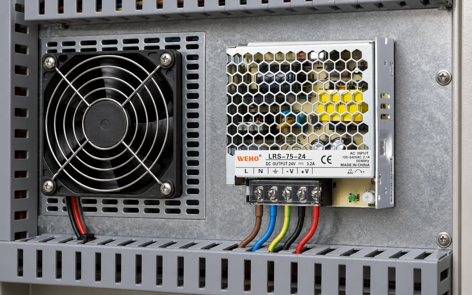
Polarity protection for a DC fan branch must be checked at the fan, including the voltage lost and heat produced by the proposed protection circuit. A 24 V supply label does not establish that an attached fan tolerates reverse connection, nor that a protective component leaves enough startup voltage.
For an OEM integrating a candidate LRS-75-24, the practical output is a protected-branch voltage and thermal budget. The fan and protection circuit remain separate products whose specifications must be verified.
Identify the fan interface before drawing the branch
A two-wire fan, a three-wire fan with tachometer and a four-wire controlled fan are not interchangeable wiring tasks. Read the fan manufacturer’s pinout, voltage limits, startup demand and signal-interface instructions. Wire colors and a similar plug are insufficient identification.
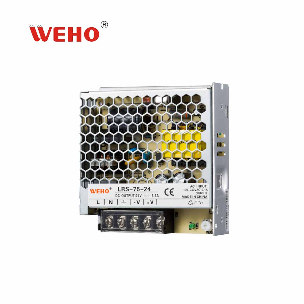
그만큼 LRS-75 product table lists a 24 V variant with a 0–3.2 A current range. Its photograph shows that exact suffix. Those facts establish a candidate source; they do not authorize a particular fan, reverse-current path or external semiconductor.
Calculate the voltage remaining after the added circuit
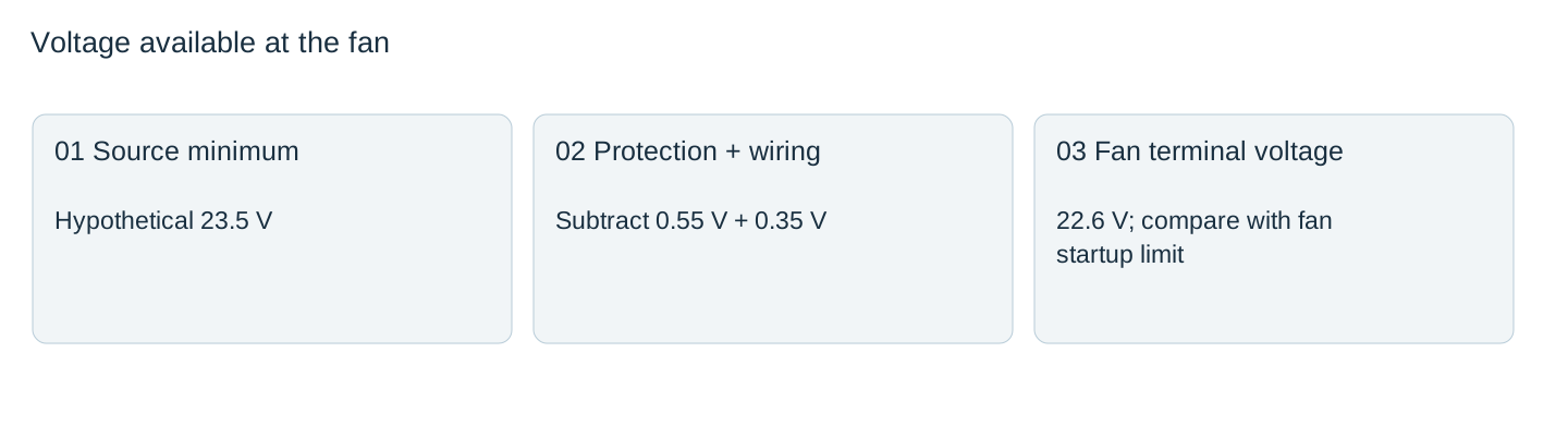
For the proposed branch, use Vfan,min = Vsource,min − Vprotection,max − Vcable,max − Vother,max. Use the fan’s required voltage at startup as well as during running. A protection device whose voltage drop depends on current or temperature must be evaluated at the relevant operating point.
In a hypothetical example, the minimum source voltage is 23.5 V, the protection drop is 0.55 V and cable plus connector drop is 0.35 V. The fan receives 22.6 V. If its documented startup minimum is 23.0 V, the proposal fails that initial screen even if its running minimum is lower.
Do not turn up the supply automatically to hide the missing margin. Other receivers on the same output must remain within their voltage limits at every permitted setting. A branch redesign may be necessary.

Treat conduction loss as a local thermal load
For a series element with a 0.55 V drop at 0.8 A, the hypothetical conduction loss is P = VI = 0.44 W. This is heat in that element, not the total fan input power or the supply loss. Its actual temperature depends on package, copper, enclosure, airflow and neighboring heat sources.
A MOSFET-based circuit has different drive, reverse-connection and startup requirements from a simple diode. TI’s motor-driver discussion illustrates that reverse-supply protection depends on the circuit architecture; its featured FET arrangement is not a ready-made circuit for any fan.
Selecting a component by its headline current alone leaves voltage rating, transient conditions, thermal resistance and failure behavior unresolved. Confirm the complete circuit with the responsible designer.
Check tachometer and control returns as well as power
| Interface | What can be missed | Verification |
|---|---|---|
| Fan power pair | Protective element changes the available voltage | Voltage at fan during defined states |
| Tachometer output | Receiver has its own pull-up and reference requirements | Fan and receiver interface documents |
| PWM/control input | Its reference may be disturbed by an improvised return-side device | Allowed reference and signal levels |
| Other branch sources | Signals can create an unintended path when power is absent | Authorized power-off interface assessment |
This is an interface review, not a recommendation to put a diode in any particular wire. Do not use PE as a fan return or assume a signal wire is protected because the main positive conductor has a protective element.
Validate the selected fan and circuit as one assembly
Record startup from the specified temperature and supply conditions, steady operation, commanded speed changes and the approved fault checks. Observe the voltage at the fan and component temperatures using a defined method. A quiet spinning fan is not a complete acceptance result.
Keep the fan part number, protection-circuit revision, source setting and wiring record together. A replacement fan can change startup current or signal behavior even when its 24 V label looks identical. Reuse this budget when evaluating the replacement, rather than carry forward an unsupported compatibility statement.
Send the LRS-75-24 fan-branch enquiry with the fan model, startup-voltage requirement, proposed polarity-protection device, PWM/tach references and measured voltage-loss record. Request the supply’s applicable operating limits, then review the fan interface and protection loss against the actual assembly.
Fan-branch protection assessment
| Operating state | Fan current evidence | Voltage at fan | Protection loss/temperature | Decision |
|---|---|---|---|---|
Blank project worksheet. Enter verified project data; example calculations above are not measurements.