Specify an outdoor lighting cable transition as an assembly: driver lead, cable entry, enclosure, connection and outgoing cable must each have evidence for their actual environment. A driver’s sealed case does not establish the protection of a joint made outside it.
그만큼 WEHO HVG-350-24 is the reference product here. Its official photograph identifies a 300–500 V AC input and a 24 V DC output. This guide helps a lighting project engineer define the external junction package; it does not approve a particular box, connector or site installation.
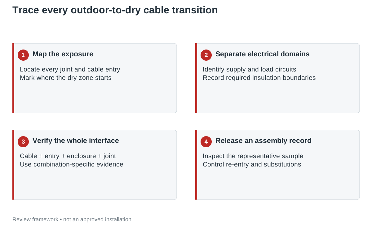
Draw where outdoor exposure actually ends
Mark the driver lead as supplied, the first external joint, every cable entry and the point at which a cable reaches a controlled dry compartment. A covered canopy, wall penetration or sealed-looking conduit is not enough to define that endpoint. Describe the actual exposure: driven rain, cleaning water, condensation, standing water or intermittent flooding, as applicable.
Separate the high-voltage supply path from the 24 V load path in the project drawing. The HVG-350-24 label identifies different electrical domains, but that does not establish that an arbitrary multiway connector or shared box is appropriate for both. Record insulation, segregation and access requirements for the complete project.
Consider water inside the connection space
WAGO’s explanation of connector moisture protection describes condensation caused by temperature changes and the resulting exchange of humid air in junction spaces. It also treats protection as a specified connector-and-enclosure combination. That is useful evidence that an apparently tight box can still require a moisture-management assessment; it is not a compatibility endorsement for the HVG driver.
Review both external entry paths and conditions that can produce moisture after assembly. Ask whether the enclosure instruction addresses orientation, drain or vent accessories, and permitted cable types. Do not add an improvised drain hole to a rated enclosure or seal a vent because it appears to be a leak. Either action changes the assembly whose evidence you are relying on.
Specify each transition with a reviewable interface record
| Transition | Record before selection | Evidence to retain |
|---|---|---|
| Driver lead to external joint | Actual lead construction, conductor identification and supplied length. | Exact driver revision and lead information; never a similar-model guess. |
| Cable through box wall | Cable outer diameter/type, entry location and enclosure wall arrangement. | Compatible entry component and enclosure assembly instructions. |
| Inside the connection space | Voltage domain, connection count, separation, operating temperature and moisture exposure. | Connector and enclosure limits for the actual combination. |
| Outgoing cable to dry equipment | Entire exposed route and the defined dry boundary. | Route drawing and the downstream enclosure requirements. |
| Maintenance or replacement | How the joint is accessed and which seals/components require replacement. | Manufacturer’s re-entry and reassembly instructions. |
Record ratings with their conditions. A connector’s immersion claim is not automatically a cleaning-jet claim. A seal selected for one cable diameter may not cover another diameter, even if both cables contain the same number of conductors.
A protected wall box can leave the transition incomplete
Illustrative layout: an outdoor luminaire’s driver is fixed under a canopy. Its output lead reaches a wall box, while the LED cable continues through an exposed conduit before entering an indoor control area. The drawing calls the wall box the dry boundary, but the outgoing route still includes an outdoor segment and another wall penetration.
Revise the boundary map to include the full route. Identify the first joint and both entries, then ask the enclosure and cable suppliers which assembled configuration covers the exposure. If a required seal or cable construction is not covered, revise the component selection before sample evaluation. Adding “IP67 driver” to the bill of materials does not close the missing route information.
Keep the schematic and physical assembly drawing distinct. The schematic identifies conductors and circuits; the physical drawing explains where the transitions sit, how cable jackets enter and which surfaces carry environmental exposure. Both are needed for an inspectable assembly.
Make the sample inspection follow the same boundary map
Before environmental evaluation, photograph the assembled entries and connection chamber. Record cable codes, entry parts, unused opening closures and assembly instructions. Confirm that the sample represents the intended production cable lengths and entry configuration. A laboratory result for a different enclosure arrangement cannot silently approve the revised one.
Set the inspection and test method from the project’s applicable requirements and the component instructions. Define what would count as water reaching a prohibited location, loss of insulation performance, corrosion or a failed connection. Have the responsible laboratory or qualified design team determine the test conditions; this article does not prescribe a universal water test.
After maintenance, review what was disturbed. An opened seal, replaced cable or substituted connector can require a new assembly check even when the driver remains unchanged. Put those re-entry rules into the installation and service record.
Give the installer a defined assembly rather than a rating slogan
The release package should identify the exact driver, environmental boundary map, electrical domains, approved assembly instructions and the evaluated sample configuration. Include the permitted replacement parts and responsibility for changes to the route or entry components.
Use the blank outdoor-junction interface record to document each transition and its evidence. Leave an unsupported interface unresolved in the project record instead of turning a product photograph into a claim that the completed installation has passed.
Use the project record
Open the blank Outdoor driver wet-to-dry transition record to record your conditions, evidence and decisions. The worksheet contains no pre-approved result.
Review the leads and environment for your lighting project
Send WEHO the HVG-350-24 model requirement, available input supply, load requirement, exposure description and proposed junction layout. Request the lead information and current installation documents needed to review the driver interfaces with the enclosure supplier.