Put 12 V and 24 V LED loads into separately specified power zones, and calculate each zone at its own voltage. A combined wattage total is useful for costing and upstream planning, but it cannot justify connecting unlike voltage loads to one fixed-voltage output. Name the voltage, modules, controller and source for each zone before comparing driver sizes.
On this page
For a sign fabricator or lighting-equipment OEM, the deliverable is a zone-to-source schedule that production and service can follow. The schedule should prevent a mechanically similar connector or replacement driver from silently changing a module’s supply voltage.
Start with the actual module and source identities
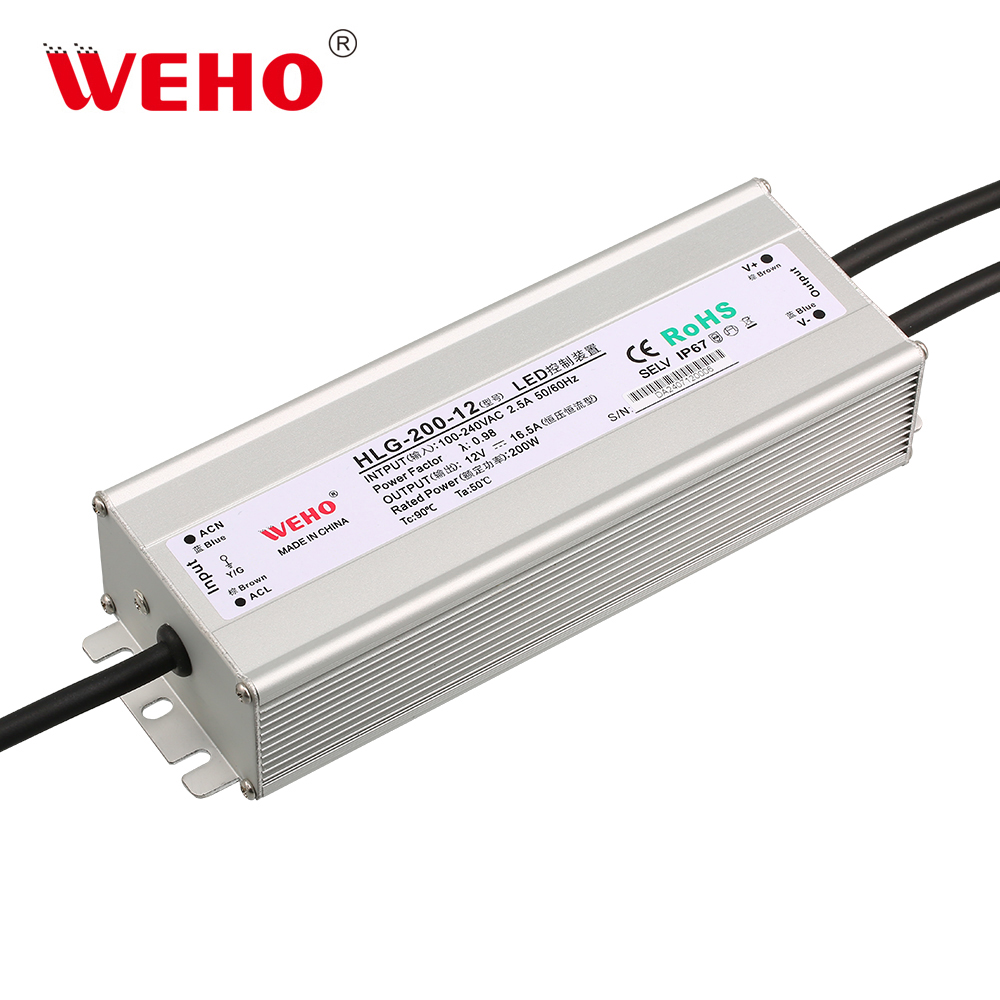
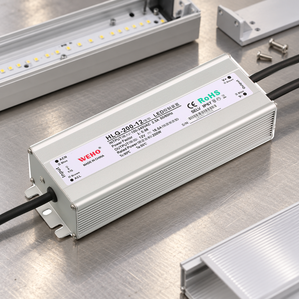
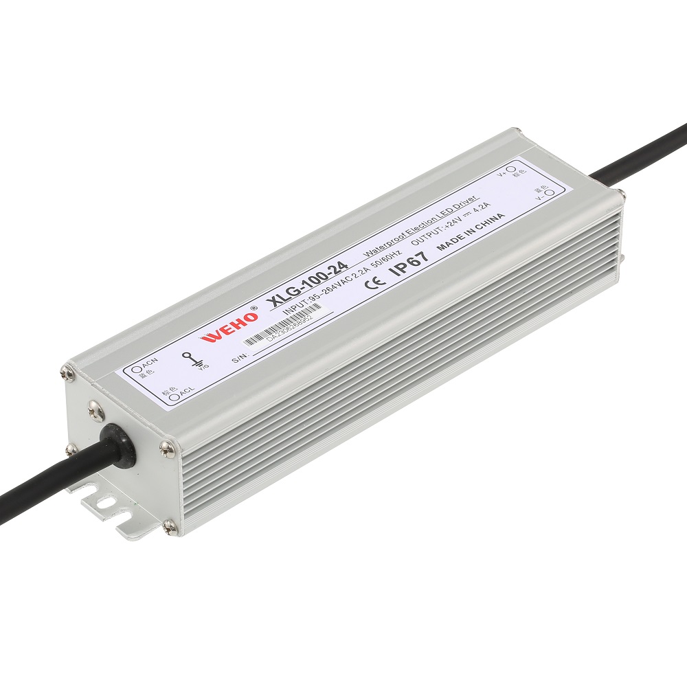
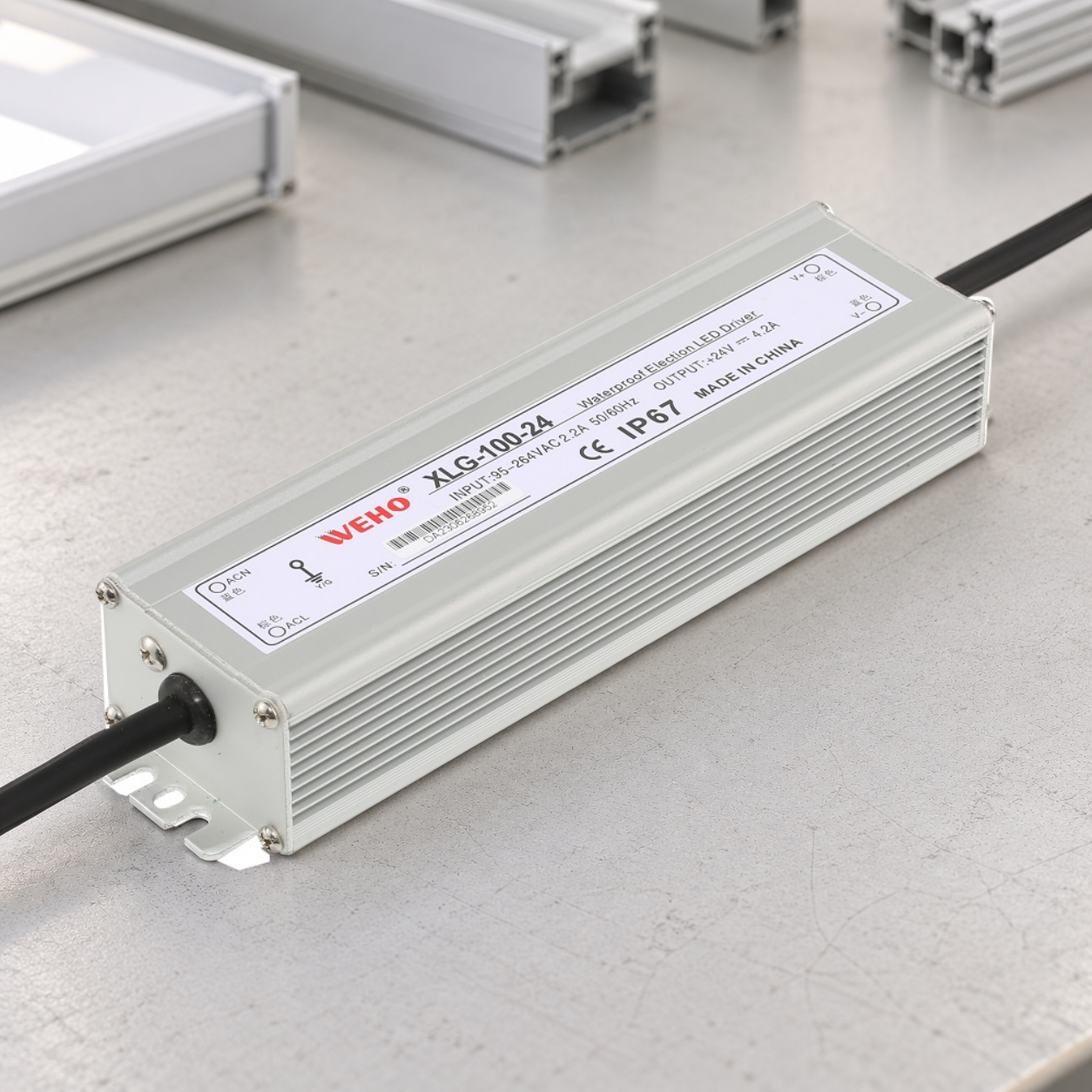
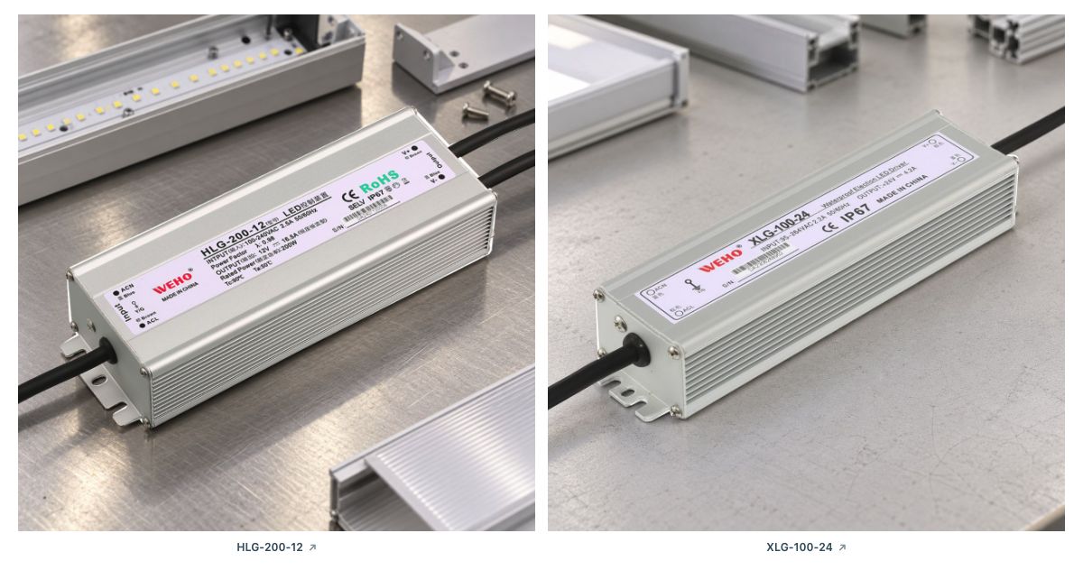
그만큼 WEHO HLG-200-12 그리고 XLG-100-24 identify two different output-voltage variants. The linked HLG-200 specification lists 12 V, 16.5 A for the HLG-200-12; the XLG-100 specification lists 24 V, 4.2 A for the XLG-100-24. The HLG variant’s nominal entries multiply to 12 × 16.5 = 198 W, while its photographed label also says 200 W. That series label is not a reason to budget 200 ÷ 12 ≈ 16.67 A; keep the variant-specific current limit and applicable operating conditions with the full suffix in the BOM.
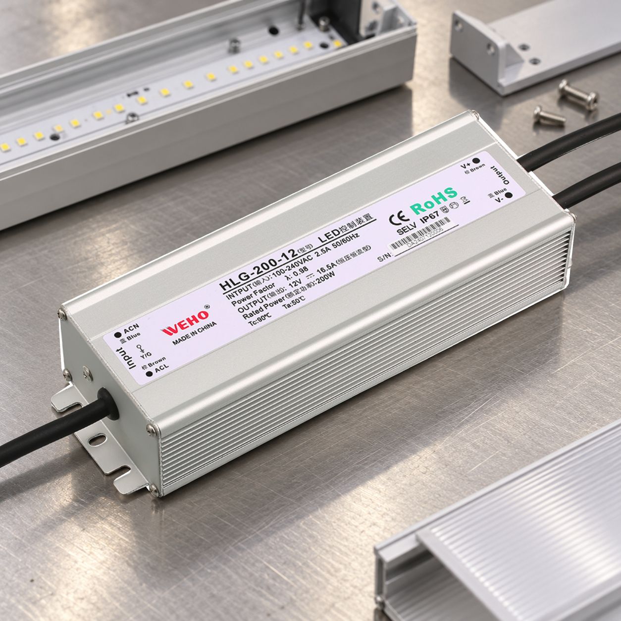
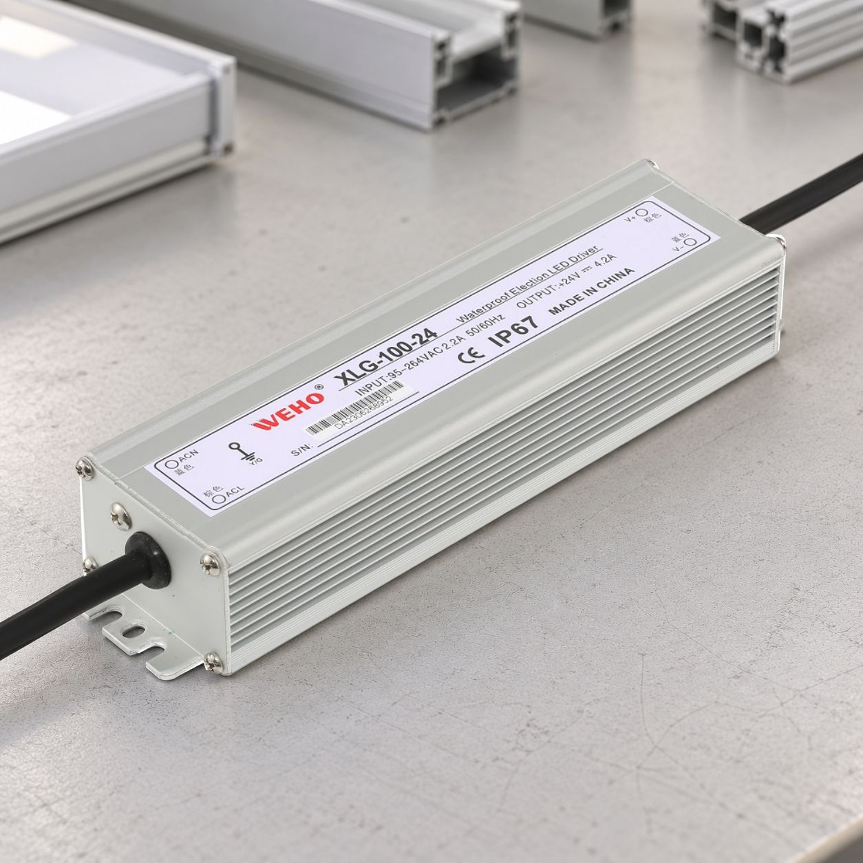
The photographs provide product identities for the voltage-zone review. They do not demonstrate that a particular LED module, controller, enclosure or installation is approved. Verify the module’s required supply type and permitted voltage range from its own documentation before making the connection plan.
Calculate the two current demands separately
Hypothetical project example: Zone A uses 12 V LED modules with a maximum simultaneous steady demand of 84 W. Zone B uses 24 V modules demanding 48 W. Assume the power figures cover all modules in their respective zones; controller and auxiliary demand must be added if not already included.
| Zone | Load calculation | Identified source for review |
|---|---|---|
| A: 12 V modules | 84 W / 12 V = 7.0 A | HLG-200-12; compare with the applicable 12 V variant specification |
| B: 24 V modules | 48 W / 24 V = 2.0 A | XLG-100-24; compare with the applicable 24 V variant specification |
The combined output-load power is 132 W. Adding 7 A and 2 A to specify a 9 A single-output driver would lose the voltage distinction: the two currents belong to different rails. Likewise, a 200 W 24 V source does not become suitable for the 12 V modules merely because the total demand is below 200 W.
The two identified sources clear only an initial comparison with their published current entries. Establish the permitted continuous output at the actual AC input, mounting and temperature conditions, then check startup and the complete connected load. No universal loading percentage or final model approval is implied by the arithmetic.
Make the voltage boundary visible in the harness
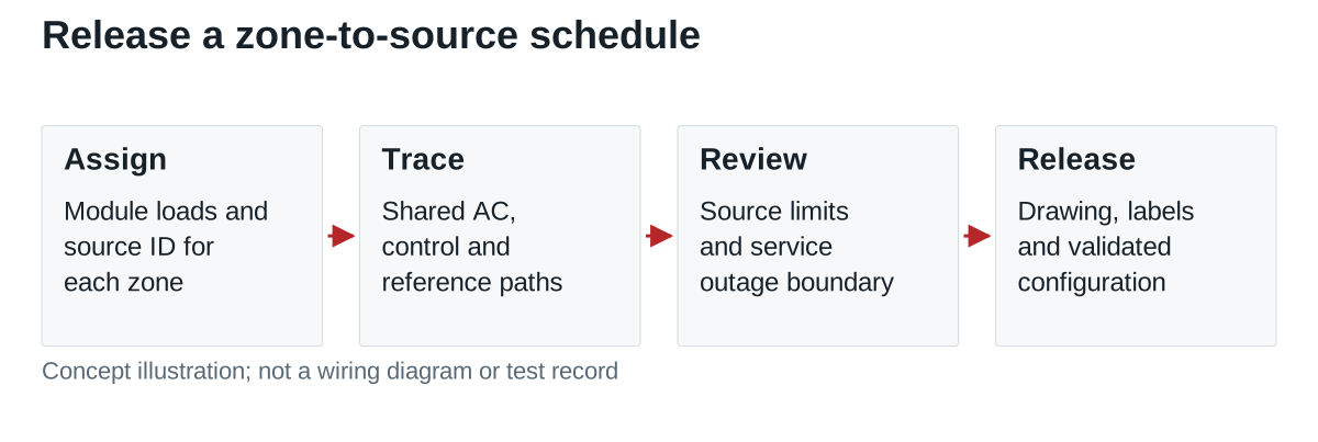
Give each source and load zone a unique ID and a stated voltage on the controlled drawing. Where connectors could be confused, specify the project’s connector identification or keying measures. A color convention can help identification, but it does not replace the circuit drawing, polarity marking or a verified connector assignment.
Do not join positive outputs or route both zones through an unqualified common output connector. Any proposed reference connection between the systems needs a separate interface review. Two DC sources in the same sign are not automatically a parallel pair, a redundant system or two independently isolated control domains.
Check the controller as a separate interface
A controller serving a 12 V zone may have a different supply or load-voltage requirement from one serving a 24 V zone. Identify the exact controller and each port. Do not infer that a shared control signal permits the two load-supply outputs to be interconnected.
Where one controller is proposed for both zones, obtain its documented supply, channel and reference arrangement. Then verify the intended combination in the assembled design. This article does not assign a dimming interface to either pictured driver or assume that one controller can accept both load voltages.
| Zone schedule field | What production and service need |
|---|---|
| Load identity | Exact LED module, required voltage and maximum simultaneous demand |
| Source identity | Full output-voltage suffix, applicable revision and installation conditions |
| Connections | Harness/connector IDs, polarity, controller ports and reviewed references |
| Service boundary | Isolation procedure, permitted replacement and checks after intervention |
Release each zone and its replacement rule
Validate the sources with the actual modules, controllers and harnesses under the project’s approved conditions. Record the voltage at the relevant terminals and the observed startup and operation of each zone. Do not use the other zone’s test result to approve an untested voltage variant.
Keep the source suffix and zone identity in the replacement list. A later purchasing substitution must preserve the required voltage and the other qualified interfaces; appearance and wattage alone are insufficient. Send WEHO your 12 V/24 V zone schedule with the exact modules, controllers and installation conditions to request an identified source proposal for each rail.