Reverse current must have a defined path and a documented limit. A DC power supply’s forward output-current rating does not establish its ability to absorb energy from a motor drive, another source, or charged downstream capacitors. Before approving an OEM power branch, identify when the output can be driven from elsewhere, what prevents unwanted backfeed, and what absorbs any returned energy.
This is a system-interface decision. A blocking device may protect the upstream source while leaving excess energy on the downstream bus. A higher-wattage source, a fuse, or an output-overvoltage protection label does not by itself resolve that energy balance.
Article sections
Separate the three events commonly called backfeed
First define positive current as flowing from the selected source to its load. Current entering the source’s positive output terminal is negative under that convention. Record the measurement direction so a minus sign in a report cannot be mistaken for a probe error.
| Event | What can drive the node | Question to resolve |
|---|---|---|
| Another source remains energized | A battery, backup rail, or separate supply holds the shared node above the inactive source output. | Does each connection block the prohibited current under powered and unpowered conditions? |
| The load returns energy | A regenerating drive or another energy-producing subsystem raises its connected DC bus. | Which rated subsystem absorbs, stores, or redirects that energy? |
| The source loses input first | Charged load-side capacitance remains energized while upstream circuitry decays. | Are reverse voltage and current permitted during that shutdown sequence? |
Texas Instruments describes reverse current arising when an output is held above its input, including input-power loss and source switching. The internal path depends on the device. Do not infer blocking from the presence of a MOSFET or from the words “power switch.”
Motor operation needs particular attention. TDK’s explanation of motor-drive effects on switching supplies discusses back electromotive force and disturbance of the source output. The motor, drive, braking arrangement, and source therefore need a coordinated review; a general auxiliary-supply specification cannot substitute for drive-system requirements.
Calculate what a capacitor could absorb in an idealized case
Suppose a hypothetical DC bus starts at 24.0 V and contains 4,700 µF of effective capacitance. Assume one load event returns 1.50 J, no other load consumes energy during the event, and no clamp or source absorbs it. Treat the capacitance as constant and ignore losses. This is an energy-screening example, not a WEHO test or a capacitor-bank design.
Capacitor energy is E = ½CV². Adding returned energy gives Vfinal = √(Vinitial² + 2Ereturned/C). Here, √(24² + 2 × 1.50 / 0.0047) is approximately 34.85 V.
If the project’s hypothetical upper bus limit is 28.0 V, the available energy headroom is ½ × 0.0047 × (28² − 24²) = 0.4888 J. The 1.50 J event exceeds that headroom by 1.0112 J. The chosen 28 V is an assumed equipment limit, not a WEHO overvoltage setting.
| Calculation output | Result | Engineering implication |
|---|---|---|
| Ideal bus voltage after one 1.50 J return | 34.85 V | Capacitance alone does not keep this hypothetical bus below 28 V. |
| Energy room between 24 V and 28 V | 0.4888 J | The rest needs another permitted destination or a different system arrangement. |
| Average returned power at two such events per second | 1.50 × 2 = 3.00 W | A small average conceals a potentially unacceptable pulse and peak voltage. |
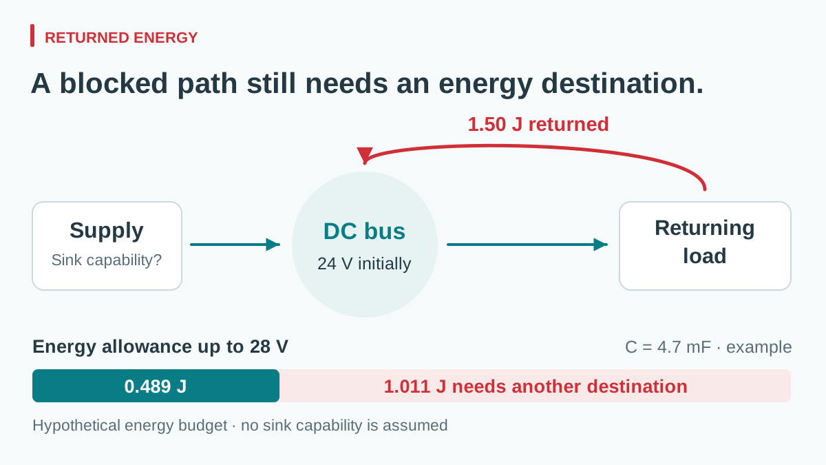
View full diagram ↗
Actual analysis needs minimum effective capacitance, starting voltage, event duration, repetition, load consumption, and the behavior of every connected source. Peak current and connection inductance also matter. Do not select a resistor, clamp, or bidirectional converter from the 3 W average alone.
Assign blocking and absorption as separate responsibilities
For a backup-fed node, a suitable blocking arrangement can prevent current entering an inactive source. Its voltage rating, continuous current, leakage, voltage loss, thermal behavior, and response during transitions must match that branch. It also needs a defined operating state when its control power is missing.
TI’s reverse-current blocking design guide demonstrates that switch orientation and back-to-back configuration change what is blocked. Its low-voltage reference circuits are explanatory examples, not ready-made protection designs for a 24 V cabinet. Verify the actual device and assembly documentation.
For a regenerative load, ask the drive-system designer to identify the energy destination. Depending on the equipment, this could involve a rated braking arrangement, a compatible storage system, or a bidirectional stage specified for that task. Adding source blocking may be part of the arrangement, but it cannot make returned energy disappear.
An overvoltage trip may stop a source from supplying further power without providing an energy sink. Likewise, galvanic isolation concerns the input-to-output relationship; it is not proof of output backfeed blocking. Keep these functions separate in the request for supplier evidence.
Use a state matrix before connecting a candidate
Give the source supplier and system integrator the same interface record. Include normal operation, source shutdown, backup takeover, load deceleration, fault recovery, and maintenance states. For each state, list which nodes stay energized and which current directions are allowed.
| Required field | Record or request |
|---|---|
| Source interface | Exact model/revision; permitted externally applied output voltage and reverse current, with duration and power state. |
| Returned event | Energy, peak current, duration, repetition, and initial bus voltage, with measurement or calculation basis. |
| System limits | Operating and absolute voltage limits of all connected receivers; agreed margin and uncertainty. |
| Blocking assembly | Direction, enabled/disabled behavior, transient response, ratings, losses, and failure assumptions. |
| Energy destination | Identified absorbing or storage subsystem and its applicable pulse, continuous, and thermal ratings. |
| Verification | Voltage/current measurement points, sign convention, sequence, limits, and responsible reviewer. |
그만큼 parallel versus redundant power-supply guide explains capacity after source loss. That calculation remains separate from reverse-energy control. The DC branch-protection guide addresses another boundary: interrupting faults and protecting the distribution path.
Do not deliberately back-drive an ordinary sample until its permitted conditions and the test protection are established. Qualification should capture source-terminal and load-bus voltage with current direction during the agreed sequence. Preserve the tested assembly identity; a different drive firmware, deceleration setting, or backup connection may create a different event.
Review NDR-240-24 as a source-side interface
If the proposed auxiliary rail uses the WEHO NDR-240-24 DIN rail power supply, identify it on the system diagram as the source being reviewed. It is not the energy absorber in the preceding example. Use the NDR-240 public specification to identify the offered variant, then request the limits that govern an externally energized output.
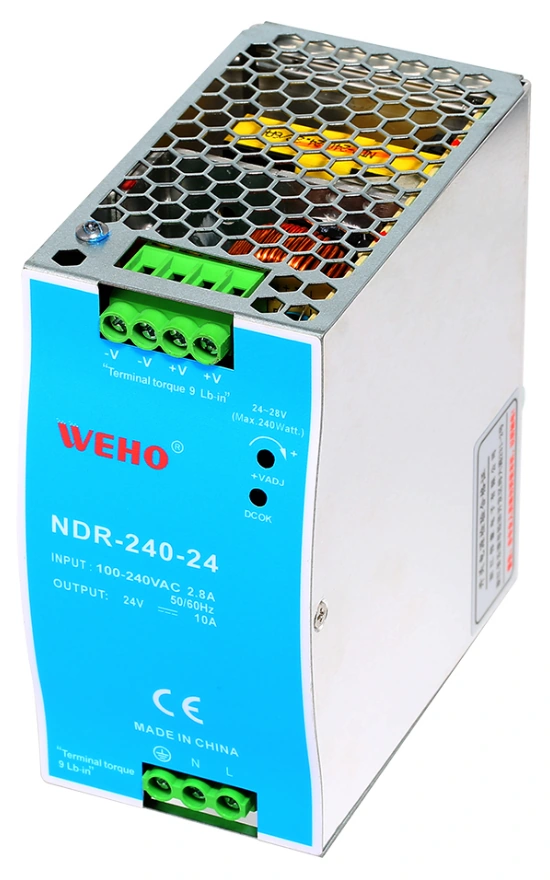
NDR-240-24 source-side reference. Returned-energy handling needs separate verification.
View original photograph ↗
Permitted back-drive conditions need a model-specific answer covering powered and unpowered states. Keep that response with the blocking and energy-destination records. If those conditions remain undocumented, do not approve the connection from the forward output rating alone.
Request source-interface evidence before a purchase decision
Ask WEHO to review the source side of your backfeed interface. Send the proposed NDR-240-24 revision, system block diagram, connected energy sources, actual starting bus voltage, maximum externally applied voltage, receiver voltage limits, and returned-event record. Include reverse-current peak, duration, repetition, and source on/off sequence. Assign the complete energy-management decision to the equipment design, rather than leaving it implicit in a power-supply order.