A resistive load bank does not necessarily draw the same current after it warms up. Measure the applied voltage and relevant hot resistance or current before attributing a changing test load to the power supply.
- Calculate loading from actual terminal conditions rather than cold nominal resistance alone.
- Check resistor ratings with their required cooling and mounting conditions.
- Keep load-bank drift separate from supply regulation and current-limit behavior.
Why does the load current change during a steady-voltage test?
Load current changes when the effective resistance or applied voltage changes. A resistor can change resistance as its temperature rises, while leads, contacts and a fan-cooled fixture introduce additional variables. A supply's voltage may also move during the same interval, so a single current trend does not identify the cause.
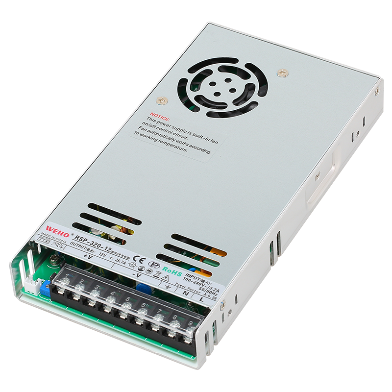
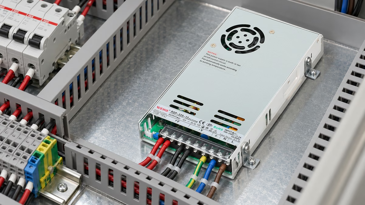
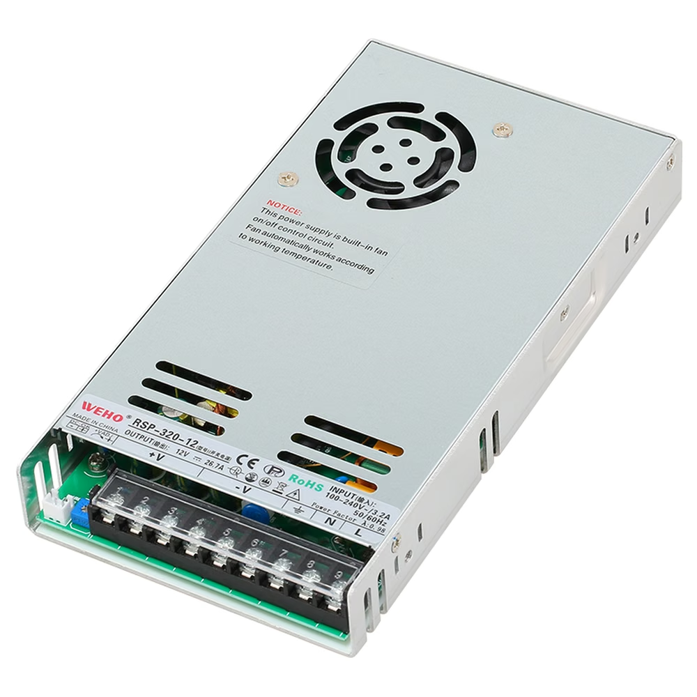
For an OEM evaluating the RSP-320 power-supply family, a bench fixture should impose a documented electrical load. The RSP-320-12 application image establishes the product context; it is not evidence of a particular load-bank test or result.
A fixture described as a “120 W load” might be rated for 120 W dissipation under specified cooling rather than draw 120 W at every voltage. A fixed resistor follows its resistance and applied voltage. A constant-power electronic load follows a different control rule and needs a different test description.
Before using a load-bank result for supplier acceptance, write the intended current or power interval and the allowed test variation. Separate that project interval from the supply's applicable output limits. Otherwise a fixture that quietly unloads as it warms can make the supply appear to have completed a heavier test than it actually did.
How large can a resistance change make the loading error?
Consider a hypothetical resistor assembly with 1.20 Ω cold resistance. At an applied 12.00 V, its initial current is I = V/R = 10.00 A, and its electrical dissipation is P = V²/R = 120.0 W. These are example inputs, not a recommended RSP-320-12 acceptance load.
Suppose the assembly's measured hot resistance becomes 1.32 Ω while the voltage across it remains 12.00 V. Its current becomes 9.091 A and its dissipation becomes 109.09 W. Relative to the initial calculation, the load has fallen by approximately 9.09%.
The percentage decrease is not 10%, even though the resistance increased by 10%. Current and power are inversely proportional to resistance at constant voltage. Use the actual ratio instead of carrying a percentage across quantities without checking their relationship.
If the load voltage instead falls to 11.80 V with the hot resistance still 1.32 Ω, current becomes 8.939 A and dissipation becomes 105.48 W. Now both voltage and resistance contribute. Separate measurements are required to assign the change to the supply, distribution path or fixture.
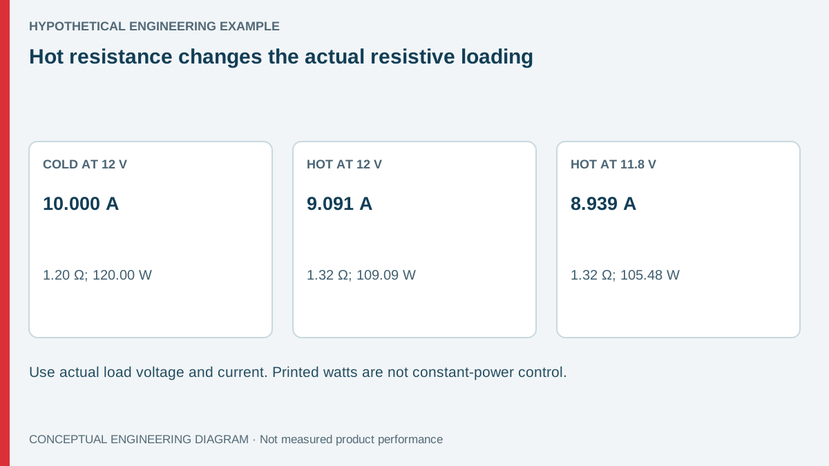
| Hypothetical state | Load voltage | Resistance | Calculated current | Calculated dissipation |
|---|---|---|---|---|
| Cold starting point | 12.00 V | 1.20 Ω | 10.000 A | 120.00 W |
| Hot resistance, unchanged voltage | 12.00 V | 1.32 Ω | 9.091 A | 109.09 W |
| Hot resistance, lower load voltage | 11.80 V | 1.32 Ω | 8.939 A | 105.48 W |
Which resistor specifications matter beyond nominal watts?
Read the resistor manufacturer's actual datasheet for the selected part. Dissipation ratings can depend on heat-sink construction, mounting surface, ambient temperature or airflow. A part's printed wattage is not permission to dissipate that power in any enclosure.
Temperature coefficient describes a change in resistance with temperature over stated conditions. It does not alone establish the assembled fixture's final operating temperature. Where a coefficient is only approximate or covers a limited range, do not extrapolate it into an unverified hot-resistance curve.
Also check working voltage, overload limits and permitted pulse duty. A resistor assembly that tolerates a brief pulse may not support the same dissipation continuously. Multiple resistors need an actual current-sharing and thermal assessment; their nameplate powers cannot automatically be added without considering how they are connected and cooled.
For source guidance, Vishay's power-resistor technical resources provide access to part-specific documentation. Use the exact selected component's requirements. Neither a generic resource page nor this article establishes the cooling arrangement for an OEM fixture.
How can the fixture be checked without creating a new error?
Measure load-terminal voltage and current during the test using equipment suitable for the circuit and expected power. Infer effective operating resistance from simultaneous or appropriately matched V/I observations where justified. An ordinary resistance function must not be connected across an energized circuit.
- Record the resistor identities, connection diagram and cold reference condition.
- Check cooling, guarding and energy-isolation provisions before energizing.
- Observe load-terminal voltage, current and relevant thermal conditions over time.
- Define stabilization using a stated trend criterion rather than an arbitrary universal wait.
- Repeat the test after changes to airflow, resistor mounting or lead arrangement.
Qualified personnel should manage hot surfaces, stored energy and exposed electrical connections according to the equipment procedure. An isolated low-voltage output can still drive substantial heating or fault current. The fixture's thermal and electrical protection needs its own review.
Use an independent shunt or current instrument only after checking its burden, range and installation requirements. A current meter can add resistance, and an unsuitable shunt can heat enough to alter its own result. The fixture should be assessed as a complete measurement path rather than as one resistor with a known nominal value.
How should supply regulation be separated from fixture drift?
Plot supply-terminal voltage, load-terminal voltage and load current against the same time reference. If current falls while the load voltage remains stable and the fixture heats, resistance change is a plausible explanation. If supply voltage also falls, investigate the operating limits and test configuration before assigning a single cause.
A lead drop belongs to the distribution path. Comparing the supply's terminal voltage with the resistor's terminal voltage helps distinguish it from internal regulation. Keep those channels separate in the report so that a good supply is not rejected for a fixture cable loss, or a receiver-voltage issue is hidden by measuring only at the source.
그만큼 RSP-320 product information identifies the relevant supply family. Check the ordered variant's applicable documentation before choosing a test load. A nominal calculation below a family's headline power does not prove that every input, ambient or installation condition is permitted.
When comparing production samples, use the same stabilized fixture state or compensate through a documented method. Starting one unit with a cold load and the next with an already hot load creates a systematic difference. Randomizing test order may reveal that problem, but it does not replace controlling or recording the actual load.
Record whether the load fan and its control are independent of the source under test. If the same output powers both the resistors and their cooling, a voltage change may alter the cooling as well as the electrical load. That feedback can complicate a comparison and should remain visible in the fixture documentation.
After replacing a resistor, repeat the relevant characterization rather than assuming the same nominal resistance and wattage produce an identical fixture. Component technology, tolerance and mounting can change the operating load even when the replacement looks similar.
Prepare an RSP-320-12 bench-load record
Send WEHO the supply identity, input condition, fixture diagram, actual voltage/current trend and cooling arrangement. State whether the objective is regulation, thermal operation or transient behavior. A time-resolved load record allows a more useful technical review than an unsupported “full load” label on the test sheet.
Frequently asked questions
Does a 120 W resistor always draw 120 W?
No. Its dissipation rating describes an allowable condition, while its actual electrical loading depends on voltage and resistance. Check both the circuit calculation and the component's installation requirements.
Can cold resistance be used for a long acceptance test?
Only if the method establishes that the resulting operating-load variation is acceptable. Otherwise record the actual current and voltage during the test and define the stabilized state used for comparison.
Is resistance guaranteed to rise as the fixture heats?
No. The direction and size depend on the component and conditions. The positive change above is an explicit hypothetical example, not a universal behavior for all resistor technologies.
Should an electronic load replace every resistor bank?
No. Choose the load method for the required behavior and accuracy. Electronic loads introduce control dynamics and operating limits of their own; a well-characterized resistor fixture can remain useful for a defined steady test.