



An active-PFC label and sufficient UPS watts do not establish a reliable UPS–power-supply pairing. Check the UPS output in each operating mode against the exact power supply’s input requirements, then verify the DC load through startup, transfer, battery operation and return to mains. Release the combination against equipment-level voltage and functional limits.
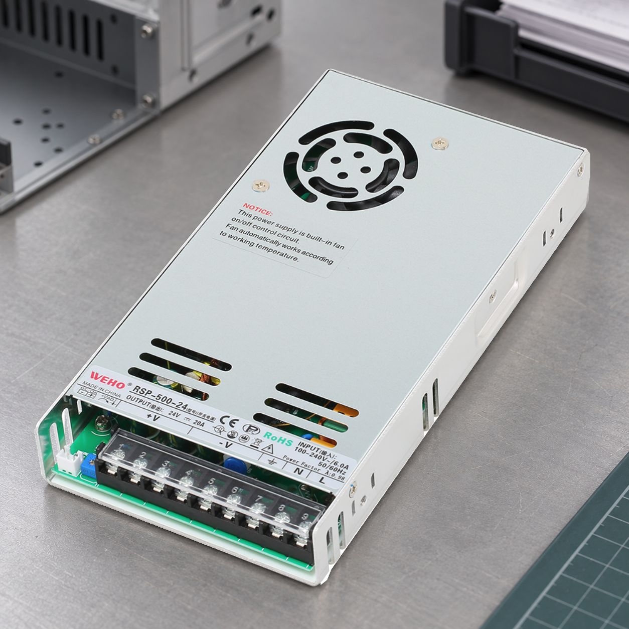
For an OEM, the question is whether its assembled equipment continues the required function when AC conditions change. A UPS that supports the average load can still require additional evidence for starting or transferring that load. Conversely, PFC alone is insufficient reason to reject a pairing without checking its documented conditions.
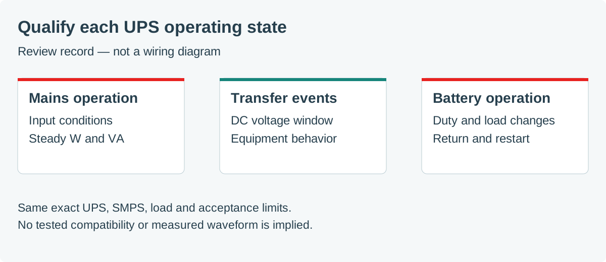
Identify the exact pair and operating modes
Record the UPS model, firmware or settings that affect its output, battery arrangement and intended supply model/revision. Obtain output voltage, frequency, waveform description and overload conditions for normal operation, battery operation and any bypass mode. The same outlet can be fed through different paths as the UPS changes state.
Compare those conditions with the supply’s documented input voltage and frequency range. Ask the manufacturers about the proposed waveform where compatibility is unspecified. Supermicro’s active-PFC UPS FAQ explicitly distinguishes a general waveform concern from a pairing it has actually tested. That IT-equipment example supports checking the exact combination; it is not evidence for a WEHO pairing.
CyberPower discusses possible incompatibility between simulated-sine UPS output and active-PFC IT loads. Treat this as a reason to obtain appropriate waveform and compatibility evidence. A sine-wave specification addresses one selection question; it does not independently prove startup capability, transfer continuity or runtime for the complete machine.
Keep watts, VA and startup separate
The UPS supplies the AC input of every connected device, rather than only the useful DC output power. Include supply losses and other loads. Check both the UPS watt rating and VA rating: Schneider Electric’s watts-versus-VA explanation states that neither limit may be exceeded.
에 대한 hypothetical steady operating point, assume 240 W of DC output, 90% efficiency and a measured total input PF of 0.95. Then Pin = 240 / 0.90 = 266.7 W 그리고 S = 266.7 / 0.95 ≈ 280.7 VA. These are calculated example values, not RSP-500-24 ratings. They exclude other connected loads and do not predict a startup pulse.
Use the PF and efficiency applicable to the actual operating mode and load. A full-load mains PF value cannot simply be assigned to light-load operation on a different waveform. Keep the detailed calculation in the AC input-budget record, and request relevant measurements when the candidate data do not cover the proposed conditions.
Next assess charging inrush, overload duration and repeated restarts separately. Ask how the UPS handles the supply’s input event, including several supplies starting together. An AC input that remains present is not proof that every downstream controller stayed within its permitted voltage window. Our multi-supply startup guide addresses that distinct branch-current problem.
Define continuity at the DC load
Set a minimum and maximum load-terminal voltage, any permitted interruption duration, and the functional behavior required during an event. Examples of functions to monitor include controller reset, communication continuity, retained data and unintended actuator outputs. Select those relevant to the machine rather than assuming “the power LED stayed on” is sufficient.
Compare the UPS’s documented transfer behavior with supply hold-up data only when their conditions and endpoints are comparable. A typical hold-up value at one input and load is not a guaranteed margin for every transfer. Measure the actual load response where that evidence is needed. Do not subtract two nominal catalog times and call the remaining number a validated system margin.
Transfer continuity and sustained backup duration remain separate requirements. A machine may ride through the transition yet run out of stored energy before completing shutdown. See hold-up time versus a DC UPS for defining the storage task; this article focuses on qualifying an AC UPS with its downstream SMPS.
Test the complete operating sequence
Prepare numerical acceptance limits before testing. Record AC conditions at the supply input and DC conditions at the actual load, together with the UPS state and equipment behavior. Qualified personnel should choose instruments and connections appropriate to the voltages and reference arrangement. Keep the wiring and load program consistent between comparisons.
On small screens, scroll sideways to compare the operating states.
| Operating state | Evidence to record | Acceptance basis |
|---|---|---|
| Normal supply | AC input W/VA/current, DC voltage and operating load. | Both devices’ documented limits and machine requirements. |
| Loss of mains | Transfer event, minimum DC voltage, resets and lost communication. | Defined voltage window and permitted interruption/function limits. |
| Battery operation | Output conditions, load changes, alarms and usable duration. | Required duty and documented UPS conditions. |
| Battery-mode cold start | Whether starting from battery is supported; startup current and DC rise. | Manufacturer-permitted mode and load startup limits. |
| Return to mains | Retransfer behavior, DC excursion and equipment recovery. | Required continuity or controlled restart behavior. |
| Repeated events | Battery readiness, restart sequence and response after partial recharge. | Declared service scenario, not a fresh-battery assumption. |
Select load extremes, temperature conditions and battery states from the intended service envelope. Do not deliberately use a mode the manufacturer prohibits. If battery-mode startup is unsupported, record that limitation and decide whether the equipment’s restart sequence can accept it.
Preserve the qualified configuration
A useful release record names the exact UPS, battery, settings, supply revision, load profile and wiring. Attach the acceptance limits and observed results for each relevant state. A change in UPS firmware, battery arrangement, supply revision or connected load should trigger a review of the affected evidence.
When a test fails, report the event and its boundary: for example, UPS overload during cold start, DC undervoltage during transfer, or insufficient battery duration. These point to different next actions. Avoid replacing the whole finding with “PFC incompatibility” until the actual cause is supported.




