Before measuring between two DC rails, establish how the oscilloscope's reference connects to protective earth and to its other channels. A probe ground clip can create a current path that the original circuit did not contain.
- Differential voltage and voltage relative to earth are different measurement questions.
- Two ordinary channel reference clips may be electrically common inside the instrument.
- Use an appropriately rated differential or isolated measurement solution when required.
Why is the ground clip part of the circuit?
A conventional earth-referenced oscilloscope commonly connects its probe reference to the instrument chassis and protective earth. Connecting that clip to a circuit node can therefore connect the node to earth. The connection must be included in the test drawing, rather than treated as an electrically invisible accessory.
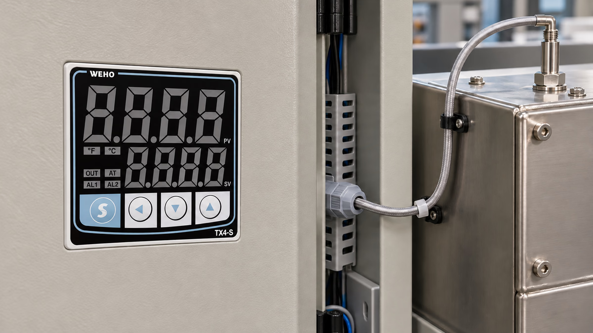
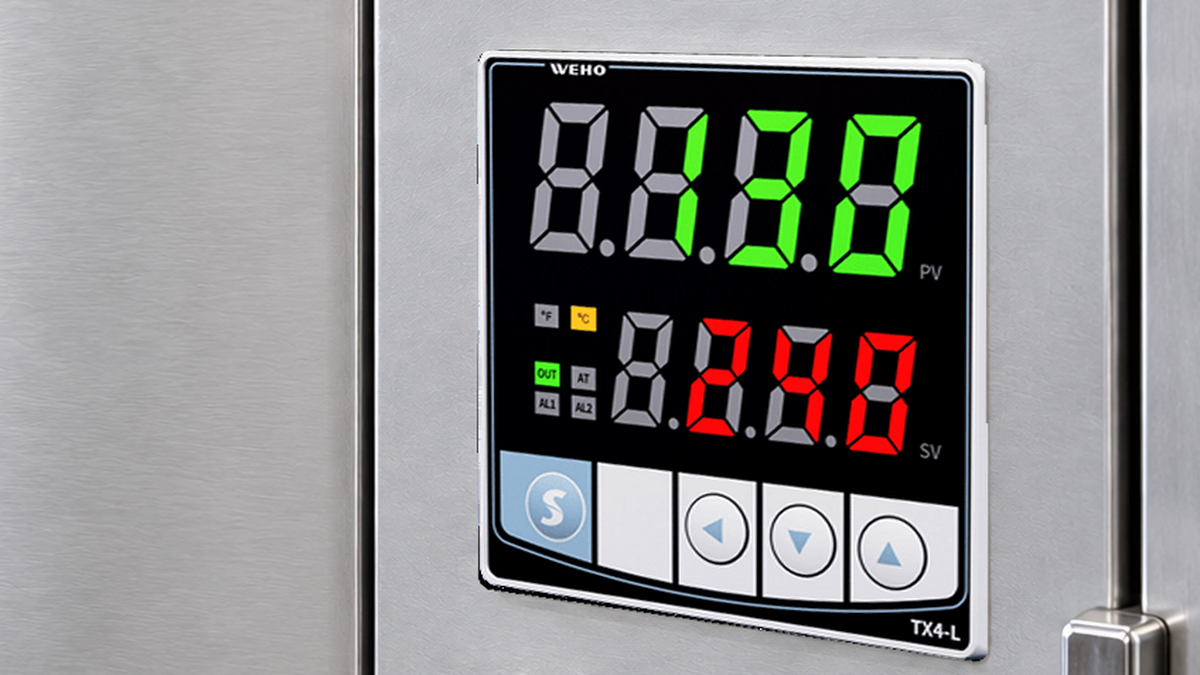
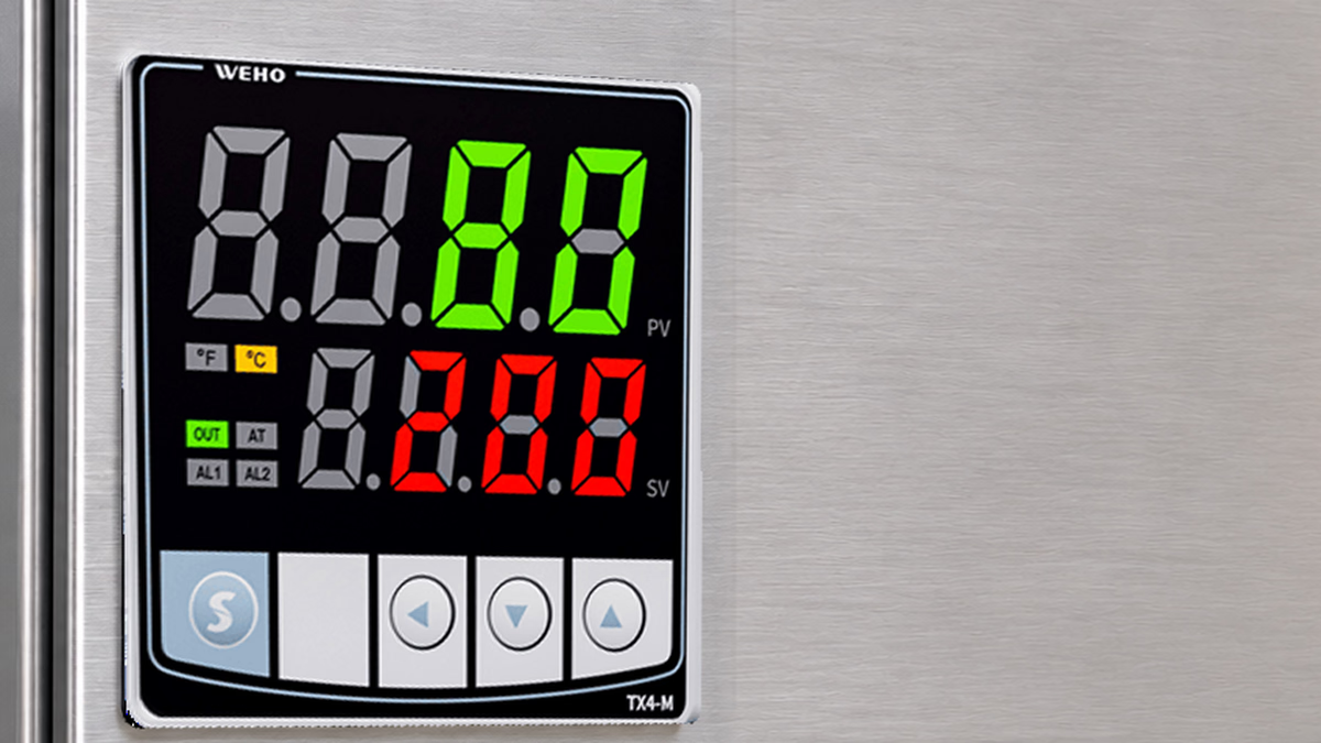
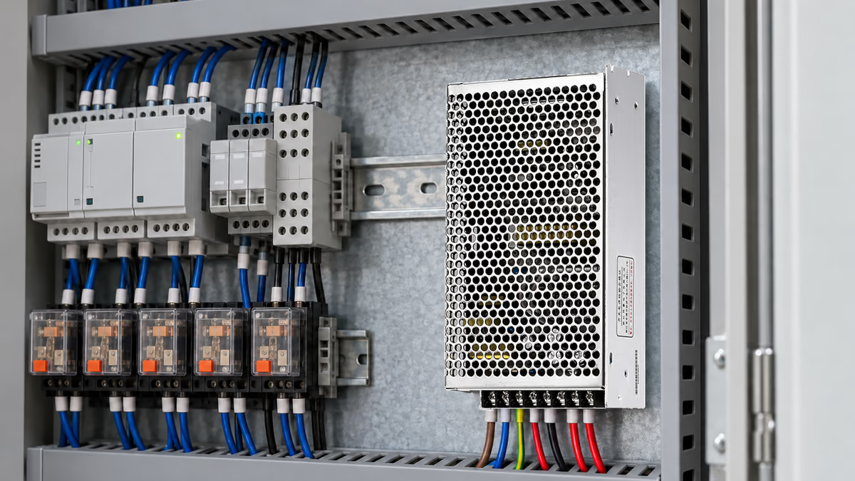
When reviewing a WEHO D-120 dual-output assembly, identify the actual ordered output combination and connection diagram. A family name alone does not establish whether rails share a return, have independent isolation or allow a particular interconnection. The illustration is a cabinet application context, not an approved oscilloscope setup.
A test can alter an otherwise floating circuit before the first waveform appears. It can also connect two nodes through the oscilloscope if different channels share their references. The result may be an invalid measurement, excessive current or damage, depending on the system and available energy.
The engineering decision is therefore about the complete measurement topology. Establish the intended quantity, instrument reference, protective bonds and other attached equipment before choosing probe connections. Computer interfaces, electronic loads and bench supplies can contribute additional reference paths that are absent from a simplified DUT diagram.
What does a shared-reference example demonstrate?
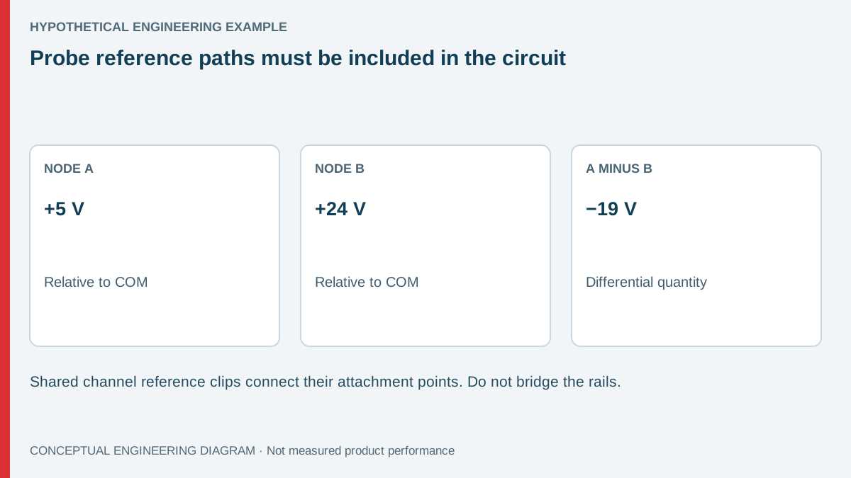
Consider a hypothetical three-node circuit with COM defined as 0 V, rail A at +5 V and rail B at +24 V relative to COM. A measurement from A to B has a signed differential voltage of 5 − 24 = −19 V. Its magnitude is 19 V, but neither node's voltage to earth has been specified.
If two conventional scope channel reference clips are connected to A and B, and those references are internally common, the instrument connects A to B through that common reference path. The original 19 V difference is now applied across an unintended conductive path. Do not perform this connection as a test.
The fault current cannot be calculated from the 19 V alone. It depends on source behavior, wiring impedance, protective devices and the instrument path. An arbitrary current estimate would add false precision and could understate the risk.
This example does not assign +5 V and +24 V to every D-120 variant. It simply shows why the desired voltage difference and the reference-clip path must be examined separately. A family photograph does not prove that a two-probe subtraction arrangement is suitable for an actual assembly.
| Planned quantity or connection | Example interpretation | Required review | Unsupported shortcut |
|---|---|---|---|
| A relative to COM | +5 V in the example | Whether COM may be referenced to the instrument | Assuming COM is already earth |
| B relative to COM | +24 V in the example | Same reference plus channel input limits | Ignoring other attached instruments |
| A relative to B | −19 V differential | Differential and common-mode ratings | Putting a ground clip on each rail |
| Two common reference clips | Conductive connection between clip points | Actual instrument architecture | Treating channel grounds as independent |
Is two-channel subtraction an isolated measurement?
No. Mathematical subtraction does not change the electrical connections made by the probes. If both channels share an earth-referenced common, their reference points remain connected regardless of the waveform expression displayed on screen.
A properly planned two-channel measurement can be useful within the instrument's applicable ratings and reference arrangement. However, common-mode rejection, probe matching, channel range and resolution also affect the result. A small difference between two large signals can be difficult to measure accurately even where the connections are otherwise appropriate.
Use the instrument manufacturer's guidance for the actual model. Tektronix's floating-measurement technical brief explains reference-path concerns and suitable measurement approaches. It does not grant permission to modify the protective-earth connection of a bench instrument.
Do not remove protective earth or power a grounded oscilloscope through an improvised arrangement to make it appear isolated. Select equipment designed and rated for the measurement. An isolation claim belongs to the exact instrument, channel or probe architecture, not to an assumption based on a battery or a plastic case.
What ratings should the measurement plan check?
Check the probe's differential voltage limit and common-mode voltage limit separately. The voltage between the two inputs can be small while both inputs sit at a substantial potential relative to earth. Frequency-dependent derating and measurement-category requirements may also apply.
Review the oscilloscope input rating, probe attenuation and expected transients. The lowest applicable limit governs the combination. A suitable probe must also provide the bandwidth, noise performance and loading appropriate to the question; a high voltage rating alone does not make it suitable for a small ripple measurement.
- Draw the DUT nodes, protective bonds and every connected instrument.
- Mark each instrument reference and any common channel connections.
- Define the desired signed voltage and expected common-mode conditions.
- Select a documented measurement solution within all applicable ratings.
- Have qualified personnel establish the guarded setup under the equipment procedure.
The diagram should include USB or network connections where they affect grounding. Removing or adding a computer during a test can change the reference network. Record the actual arrangement used for the accepted result so that a later repeat does not quietly introduce a new path.
How should the result be documented for a supplier?
Report the voltage quantity and its reference explicitly: A-to-COM, B-to-COM or A-to-B. Include probe type, attenuation, coupling, bandwidth and operating state. A screenshot without the reference information can be impossible to interpret and may hide a measurement-induced fault.
Distinguish unexpected DUT behavior from the effect of attaching the instrument. If the output changes when a probe is connected, stop and review the topology under the appropriate procedure. Do not continue moving ground clips around an energized assembly in search of a cleaner display.
The D-120 family product page is the product entry for obtaining the relevant variant information. Use the applicable diagram for actual rail definitions. This article's three-node example is not a substitute for that documentation or for the instrument manual.
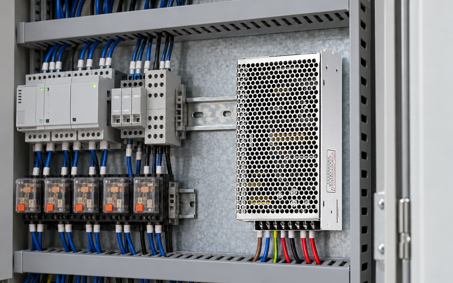
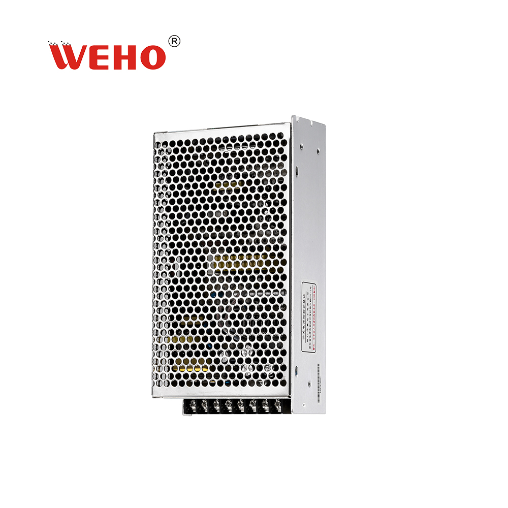
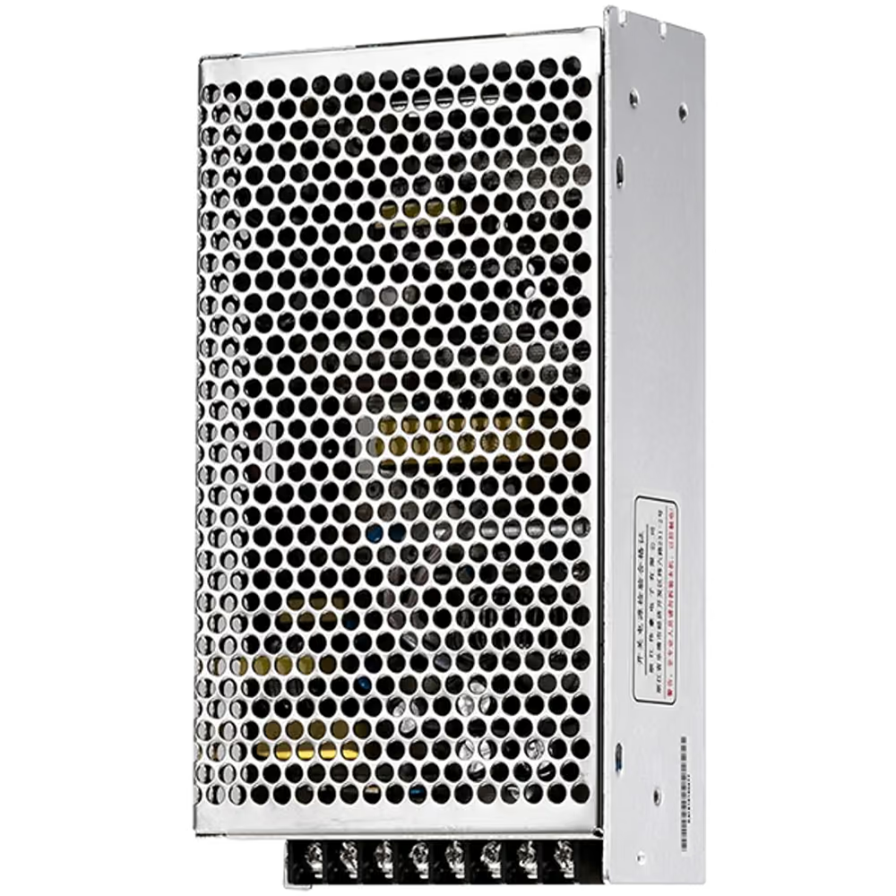
The supply image below remains an identity reference. It does not show internal insulation, approved earth bonds or the absence of other reference paths. Keep those claims in the verified electrical documentation, where the reviewer can evaluate them directly rather than infer them from an enclosure photograph.
Include the instrument's connection state in any fault investigation. A result obtained with an isolated laptop on battery can differ after a grounded charger is attached, depending on the actual interfaces. The test record should preserve that distinction without guessing that every computer connection is isolated or grounded.
The review should also identify which nodes may change potential during startup or a fault. A valid steady measurement arrangement is not automatically valid through every transition. Check the applicable probe and instrument limits for those conditions before selecting the capture method.
Prepare a dual-output measurement review
Send WEHO the ordered variant, rail drawing, intended measured quantity and complete instrument connection sketch. Include any observed change when the measurement system is attached. This supports a focused discussion of the supply interface while leaving instrument selection and electrical work with the qualified personnel responsible for the test.
Frequently asked questions
Are the two channels of a scope always isolated?
No. Check the exact instrument architecture. Many conventional bench instruments share channel references and protective earth, while some purpose-designed instruments provide isolation under specified ratings and conditions.
Does a differential probe remove every measurement limit?
No. Differential voltage, common-mode voltage, bandwidth, loading, transient and environmental ratings still apply. Check the complete probe-and-instrument combination for the intended circuit and signal.
Is a DC output's negative terminal necessarily protective earth?
No. That relationship depends on the equipment design and documented connections. Do not add a bond simply because it makes probing more convenient or because another installation uses one.
Can the example determine the resulting short-circuit current?
No. It shows an unintended connection but does not specify the source impedance or protective response. Those must be established from the actual system; the voltage difference alone is insufficient.