The right electronic load for testing a power supply is the one that reproduces the behavior relevant to your decision. Constant current, resistance, power and voltage are different control laws. Selecting a convenient front-panel mode can change the stress applied to the supply and the conclusion drawn from a test.
On this page
For an OEM validation engineer, start with a short description of the real load: what does it demand when the supply voltage changes, and what happens during startup or a transient? Choose the electronic-load mode from that behavior, then verify that the instrument can reproduce it over the required operating range.
Match the mode to the question
Keysight’s electronic-load overview identifies the four common modes: constant current (CC), constant resistance (CR), constant power (CP) and constant voltage (CV). The controlled quantity is the first selection criterion. A mode’s name does not guarantee operation outside the instrument’s specified envelope.
| Mode | What the load tries to maintain | A useful test question |
|---|---|---|
| CC | A programmed current | Can the supply regulate at specified current levels or load steps? |
| CR | A programmed resistance; current changes with voltage | How does the source behave with a resistive demand? |
| CP | A programmed power; current increases as voltage falls | How does the source respond to a downstream load approximating constant input power? |
| CV | A terminal voltage by adjusting the current it sinks | How does a current-regulated source behave against a controlled terminal voltage? |
A load can represent one part of a device’s behavior without reproducing all of it. A downstream converter may look approximately constant-power within its regulation range, but its startup threshold, input capacitance, current limit and shutdown behavior remain separate characteristics. A single CP setting does not reproduce that complete converter.
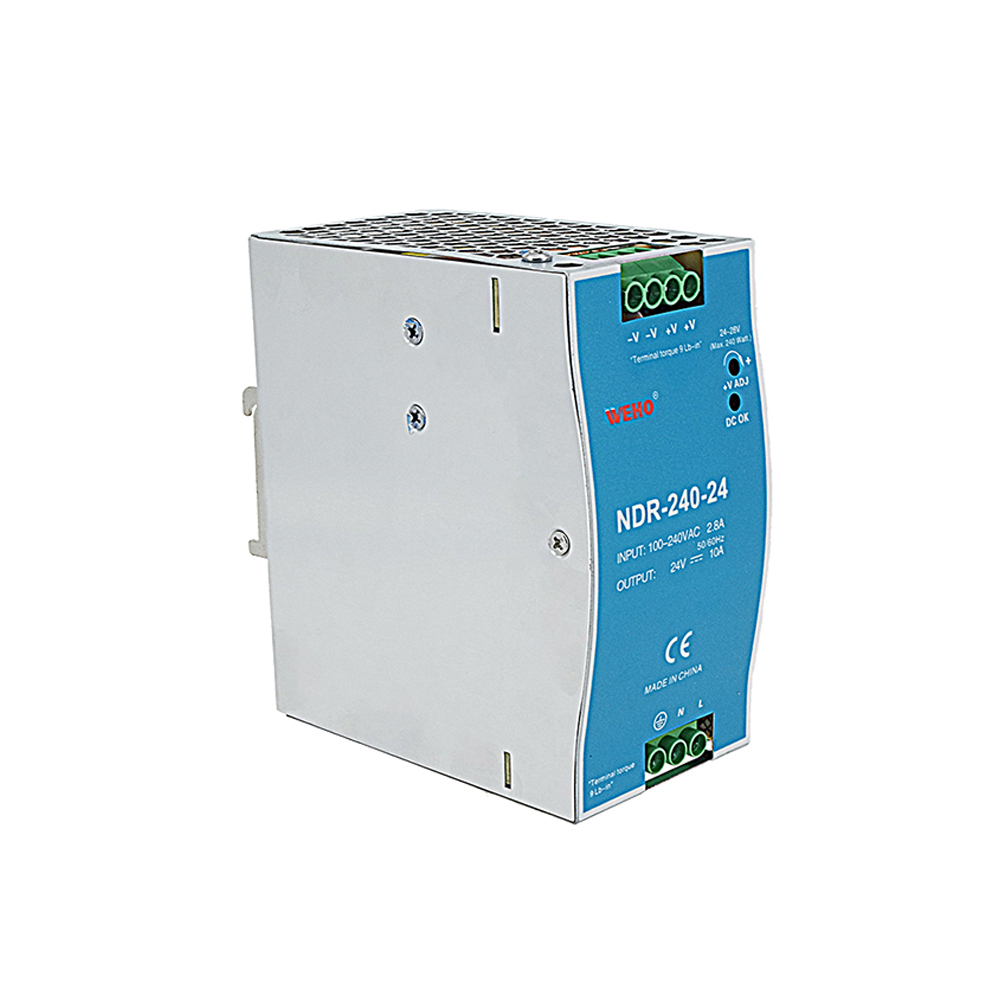
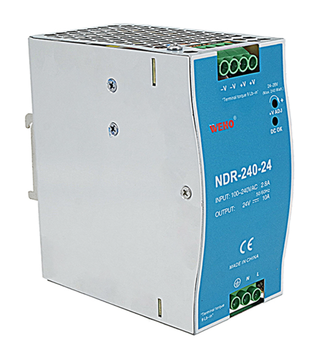
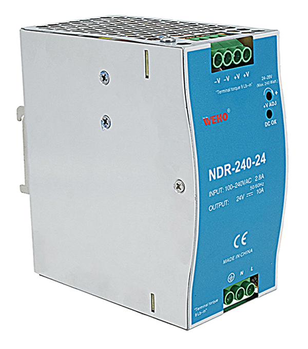
The WEHO NDR-240-24 illustrates the source side of this decision: its public NDR-240 specification lists 24 V and an output-current range of 0–10 A for this variant. Choose the load instrument against the required test points and its own operating envelope. The NDR-240-24 is a power source, and the 48 W mode comparison below remains hypothetical.
See how three modes diverge during a voltage dip
Suppose three hypothetical tests begin at 24 V and 48 W. Set CC to 2 A, CR to 12 Ω, and CP to 48 W. At the starting voltage, all three demand the same current and power. Their demands diverge if the source voltage falls to 18 V.
| Programmed mode | Current at 24 V | Current at 18 V | Power at 18 V |
|---|---|---|---|
| CC: 2 A | 2.00 A | 2.00 A | 36 W |
| CR: 12 Ω | 2.00 A | 1.50 A | 27 W |
| CP: 48 W | 2.00 A | 2.67 A, rounded | 48 W |
These values follow I = V/R and P = VI, assuming each mode remains in control. The CP demand is 48/18 = 2.666… A. If the load’s current limit or low-voltage boundary prevents that current, the actual test no longer represents ideal 48 W operation. Record the limitation instead of reporting the setpoint as the achieved load. For startup work, record any programmed load-on voltage and the instrument’s actual low-voltage behavior.
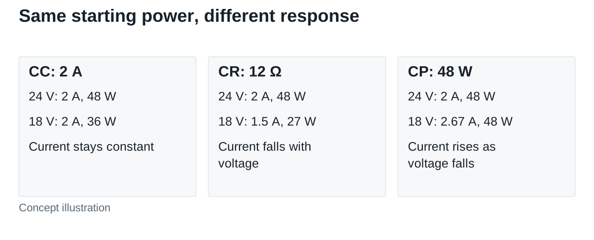
This comparison explains why a supply that passes a resistive test has not automatically passed a constant-power test. It also explains why forcing every real load into CC can conceal a relevant voltage-dependent demand.
Use CV as a sink, with the correct source
CV operation deserves a separate check. In the Keysight EL30000 user guide, CV mode controls terminal voltage by sinking current, subject to its limits. This is useful when the source under test is intended to regulate current. It is not a promise that the load can supply missing energy to hold a rail up.
When a stiff voltage-regulated supply and a CV load demand incompatible terminal voltages, current can move toward a configured or physical limit. Decide which device is intended to regulate voltage and what limits define the test. For a battery or another device that must both deliver and absorb energy, confirm the required operating quadrants; a conventional sinking load alone does not provide a complete bidirectional simulator.
Check the full operating envelope
Use the selected instrument’s voltage-current-power operating area, minimum operating voltage, channel configuration and cooling requirements. Keysight’s Power Handbook explains electronic-load operating modes and the need to remain within the allowed voltage, current and power envelope. Maximum voltage, maximum current and maximum watts are not necessarily available together.
For an independently calculated example, an instrument limited to 200 W cannot sustain 30 V at 10 A, because that point requires 300 W. Check any time-limited overload region separately rather than treating it as a continuous rating. At the other end, a load may lose current-control capability as voltage approaches zero; a high headline wattage does not resolve that boundary.
For dynamic work, specify both load levels, slew rate or transition time, dwell times, repetition rate and the required measured waveform. A programmed fast step is not evidence that the same current transition occurred at the DUT terminals. Connection impedance, measurement arrangement and the instrument’s response affect the achieved test.
Keep a record that makes the result reusable
Keep the supply model and revision, input conditions, load instrument and firmware, selected mode and range, setpoints, limits and timing together. Identify the voltage measurement point, record any instrument voltage-sense configuration used, and save the actual current and voltage traces needed for the decision. A front-panel current average alone cannot establish the shape of a short transient.
State the acceptance rule before collecting results. It might concern steady output tolerance, a permitted transient excursion, or recovery within a time window. Use the rule relevant to the equipment; this article does not prescribe a universal ripple or transient limit.
Approve the method when the selected mode represents the intended demand, the instrument remains within its documented envelope and the achieved waveform supports the acceptance decision. Hold the result if compliance, bandwidth or a protection limit changes the test. Change the method when the real load needs behavior the chosen mode cannot reproduce.
Send WEHO the supply model, intended load behavior, operating conditions and acceptance limits to discuss the documentation and validation requirements for your application.