Compare the interruption at the receiver’s AC input with that receiver’s documented or verified hold-up behavior. A nominal transfer-time claim and a successful lamp demonstration cannot establish whether a controller, computer or process will remain operating.
This guide helps an integrator evaluate allowed states involving the WEHO WHPU-2500 inverter/charger family. It does not claim the product has an automatic transfer relay, bypass path or UPS classification.
Establish which state transitions the system actually permits
Obtain the exact unit’s operating-state description before planning a source-loss test. A charging input may have a different relationship to the output from the one an installer expects. If switching is external, identify that equipment and its controlled sequence separately.
Choose only manufacturer-supported transitions for the assembled system. Define normal conditions, source loss and restoration, and the relevant receiver operating state. Keep neutral/earth and protective-device design in its own competent review; this article concerns output timing and receiver continuity.
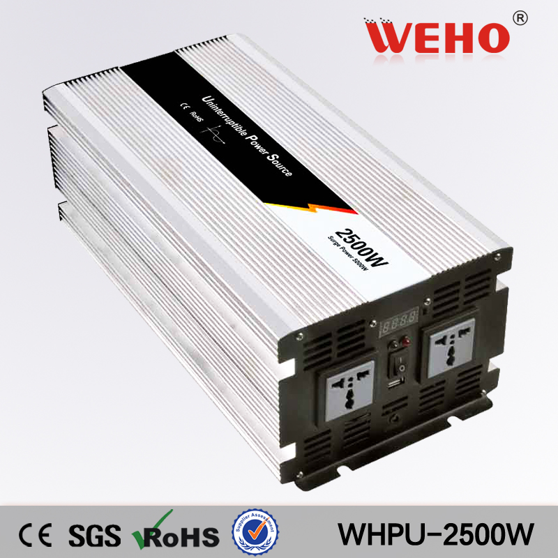
The WHPU-2500 page identifies a pure-sine inverter/charger and several DC/AC options. It does not provide a complete output-interruption specification that can approve a particular receiver.
Choose a receiver-relevant interruption definition
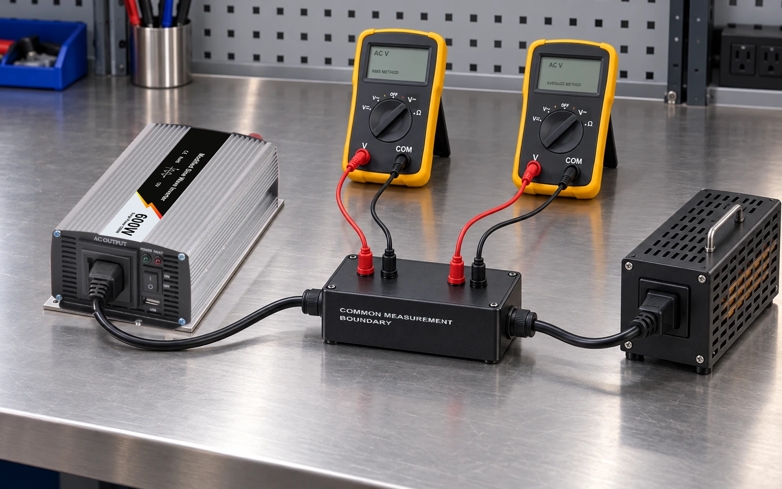
Write down what counts as lost supply for the receiver: a specified input envelope, a defined measurement method, or the applicable manufacturer test criterion. An AC waveform normally crosses zero, so one arbitrary instantaneous voltage threshold can confuse normal zero crossings with an interruption.
Schneider Electric’s ATS timing explanation illustrates that the chosen measurement points and definition affect a switching-time result. Its equipment-specific timing numbers do not define WHPU behavior.
Record the first and last samples or events used for the interval and retain the waveform. If a report gives only “12 ms transfer,” ask what began and ended that interval and under which load/source conditions.
Define the load’s behavior, not only its power rating
Obtain the receiver’s applicable interruption or hold-up information at the intended input and load. A receiver’s internal output may remain active after its AC input is lost; the duration can vary with load and pre-event conditions.
If the requirement is uninterrupted process operation, record the process consequence too. A display that remains lit may coexist with a controller reset, communications loss or data corruption. Identify the actual release criterion, such as no reset and completion of a defined transaction.
Do not transfer a hold-up value from a different receiver, input condition or hardware revision. If no relevant specification exists, use an agreed qualification method instead of filling the gap with a typical number.
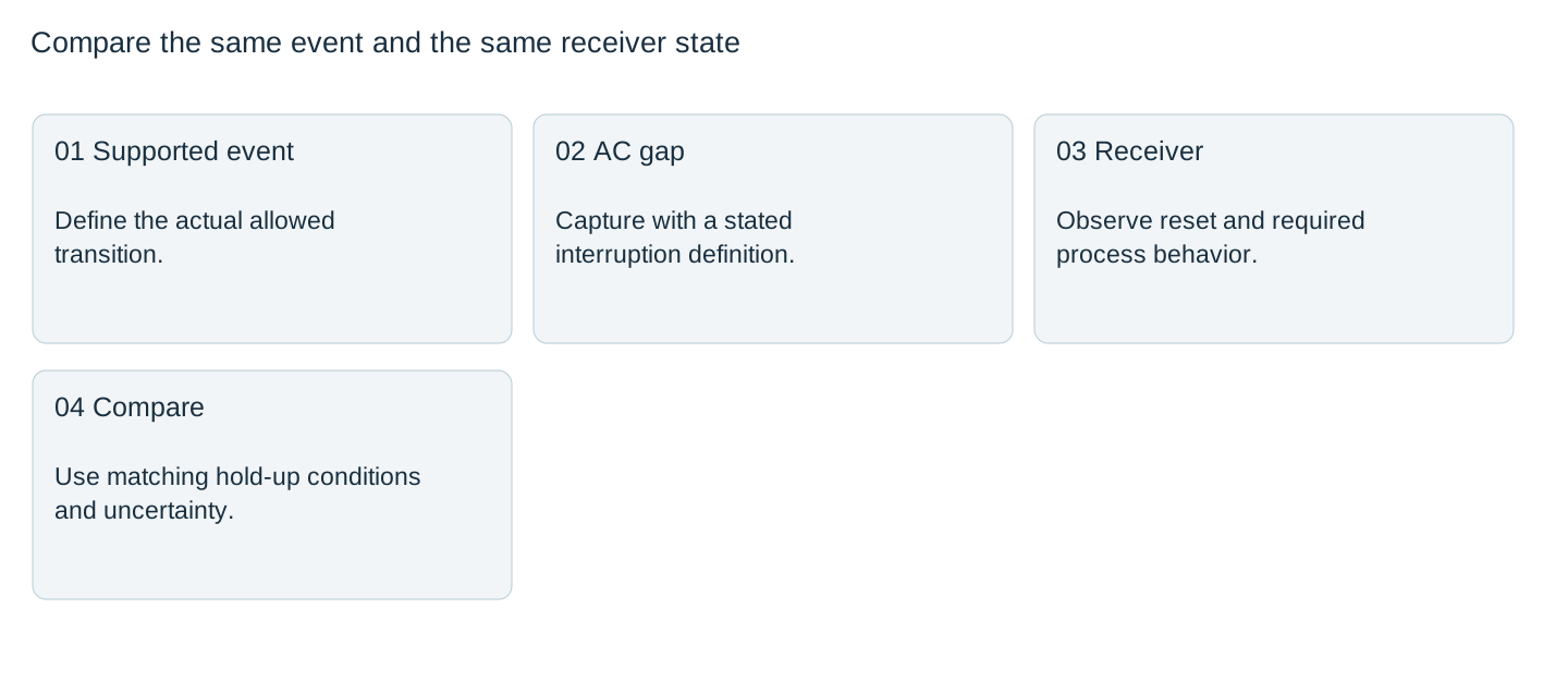

Compare timing on the same basis
Consider an illustrative case with a defined 18 ms output interruption and a receiver validated to tolerate 12 ms under matching conditions. The gap exceeds the validated interval by 6 ms, so this evidence cannot approve continuity. If a later interruption were 8 ms, the 4 ms arithmetic difference would still need the agreed uncertainty and condition coverage.
These are hypothetical timing values. They are not WHPU-2500 measurements or general UPS limits. A shorter observed gap cannot approve untested load states or all possible source restoration events.
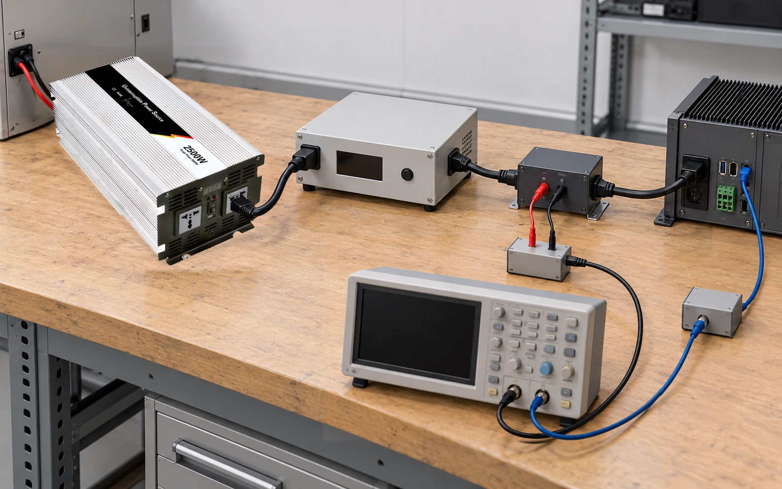
Capture the relevant AC behavior and receiver status on a common time basis using suitable, safely connected acquisition equipment. A phone video of a lamp is not a reliable millisecond measurement or a receiver reset log.
Release the covered continuity result
Retain exact hardware, source configuration, load state, event, measurement definition, raw data and receiver response. Document the conditions actually covered, including any uncertainty relevant to a close comparison.
If continuity fails, consider a different receiver interface, a documented energy buffer or equipment that supports the required supply behavior. Do not improvise parallel AC connections or assume a larger inverter wattage removes a timing gap.
Repeat affected checks after changing switching equipment, receiver hardware/firmware, source conditions or the inverter configuration. The result should say which receiver functions survived which defined transition, rather than labeling the whole system“uninterruptible” from one demonstration.
Specify the continuity requirement
Provide WEHO with the exact WHPU-2500 configuration, documented state transitions, receiver hold-up requirement and timing method. Request the operating information needed before evaluating output continuity.
Output-gap and receiver-continuity record
| Event / load state | Output gap and raw trace | Receiver status / process result | Hold-up basis | Coverage / decision |
|---|---|---|---|---|
Blank project worksheet. Enter verified project data; example calculations above are not measurements.