When comparing linear vs switching power supply noise for audio, test or measurement equipment, begin with the sensitive load’s requirement. Define the rail, relevant frequency band and acceptable disturbance before comparing products. “Linear”, “switching” and “low noise” are descriptions, not proof that a complete system will meet its audio or measurement target.

Separate the main supply from the sensitive rail
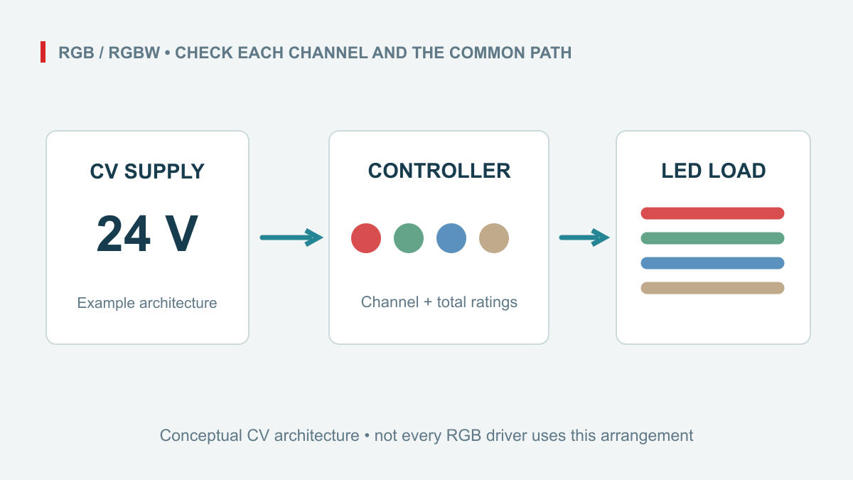
A machine may distribute 24 V to several modules while an analogue section uses local regulation. The noise requirement at that analogue rail can differ from the requirement at the cabinet supply terminals. Write down where each limit applies, which loads share the source and which stages sit between the source and the sensitive circuit.
A linear supply is not automatically silent in every installation, and a switching supply is not automatically unsuitable for every precision load. The useful comparison is the documented result under relevant conditions, including the downstream circuit. Any proposed local regulator or filter needs a circuit-specific design; adding one is not a guarantee of compliance.
What the DRP-240-24 evidence actually says
The matched sheet for the DRP-240-24 lists 24 V output over a 0–10 A current range. Its 24 V column gives 80 mVp-p in the wave-and-noise row. The 48 V model has a different figure, so the family name alone is insufficient for comparison. The WEHO product navigation lists the DRP-240 series for further product review.
This single-page sheet does not supply a complete bandwidth, probing and load-condition protocol for that noise entry. Treat 80 mVp-p as the documented entry, not as a measurement from the illustrated installation. It does not establish audio signal-to-noise ratio, converter resolution, sensor accuracy or an “ultra-low-noise” classification.
| Available evidence | What it does not establish |
|---|---|
| Exact 24 V/10 A model and source photographs | Compatibility with every 24 V instrument or audio module. |
| 80 mVp-p wave/noise entry | A comparable RMS value without waveform and measurement conditions. |
| Original DIN-rail housing and terminals | Correct grounding, shielding or noise performance of a complete cabinet. |

Make the comparison measurable
Ask both candidates to be evaluated with a defined input condition, representative load, measurement point and bandwidth. Keep peak-to-peak and RMS values distinct; they cannot be converted by a universal factor for an unspecified noise waveform. Identify whether the concern is a periodic component, a broad-band disturbance or a transient event.
The measurement arrangement matters. The referenced output-ripple measurement guidance explains that a probe ground loop can pick up surrounding noise and increase the apparent ripple. Record the setup so that a change in probing is not mistaken for an improvement in the supply.
Measurements on mains-powered equipment require suitable instruments, isolation practices and qualified personnel. Do not remove protective earth or improvise a grounded probe connection to reduce a displayed waveform. The test method must be safe and appropriate to the electrical reference being measured.

Check coupling paths and installation separately
Review where power conductors, signal cables and switched loads run. The receiver documentation should guide its grounding and shielding arrangements. A clean result at a supply terminal does not by itself prove the same result at a distant sensitive module, particularly when other loads share wiring or returns.
The photographed DRP-240-24 uses its original rear DIN clip. Its round screw-access openings are distinct from the rectangular conductor entries. Keep that physical distinction when building the panel, and retain ventilation access. The sheet’s size table and drawing differ slightly at 125.2 versus 125.5 mm for the main face dimensions; confirm the supplied drawing for critical clearances rather than silently choosing one.
Frequently asked questions
Can 80 mVp-p be used as an audio-noise specification?
No. It is a power-supply sheet entry. Audio performance requires a defined signal path, bandwidth and measurement method at the relevant system points.
Does choosing a linear supply remove the need for testing?
No. Load behaviour, local regulation, grounding and the measurement setup still matter. Compare the complete requirement with the complete result.

Prepare a rail-specific enquiry
Send the voltage and current requirements, sensitive-load documentation, required metric and frequency band, distribution layout and proposed measurement method. State whether the supply feeds a sensitive circuit directly or through another stage. Ask WEHO for the matching model and available test conditions, then qualify the complete system before making a low-noise performance claim.