



- Integral windup can delay recovery when accumulated control demand exceeds what the actuator can deliver.
- A controller output limit and a downstream power limit are different constraints.
- Record requested output, applied output and temperature together before changing tuning.
- Do not assume TX4-S provides a particular anti-windup algorithm or external tracking input.

Why an intact heating system can recover slowly
A heating process spends a long interval below its setpoint while available actuator power is restricted. After the temperature reaches the target, output stays high longer than expected even though the actuator responds to its command. Investigate accumulated integral demand and the location of the limiting function before treating the behavior as a failed switching device.
The TX4-S PID controller reference supplies the product context. A front-panel PID label does not reveal how its internal algorithm handles saturation or whether it receives downstream actuator feedback. Confirm those details for the applicable configuration before assigning a corrective feature.
Separate control demand from physically applied output
Integral action accumulates error over time to address persistent offset. OMRON's temperature-control overview explains the role of proportional and integral actions in temperature regulation. The same accumulation becomes a problem when additional demanded output cannot produce additional actuator effort.
Use three separate quantities in the review: the calculated demand before limiting, the controller's limited command and the actuator's applied output. A downstream power manager can restrict the third quantity even when the controller has already limited its own command. A controller cannot automatically infer every external constraint from its nominal output range.
MathWorks' anti-windup example demonstrates how saturation can create delayed recovery and describes several control approaches. These are general algorithm examples, not proof that a WEHO controller implements those approaches. Use them to frame the evidence request and the test record.
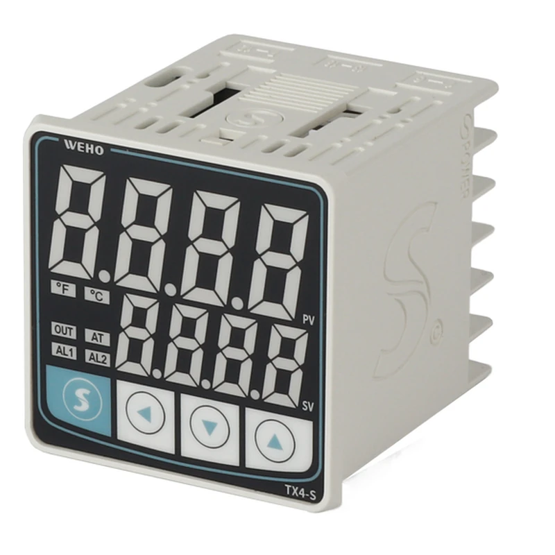
Also distinguish a slowly responding process from an integrating controller that has lost contact with an actuator constraint. Sensor lag, thermal storage, actuator limits and controller state can coexist. A temperature trace alone cannot isolate which mechanism dominates the return to normal operation.
Calculate an illustrative windup-and-recovery record
This hypothetical arithmetic model uses proportional-plus-integral action with no derivative term, filtering or anti-windup. Let e = setpoint − measured temperature, u* = Kp × e + xI, and dxI/dt = Ki × e. The model is deliberately simplified; it is not the disclosed TX4-S algorithm or a prediction of an actual oven.
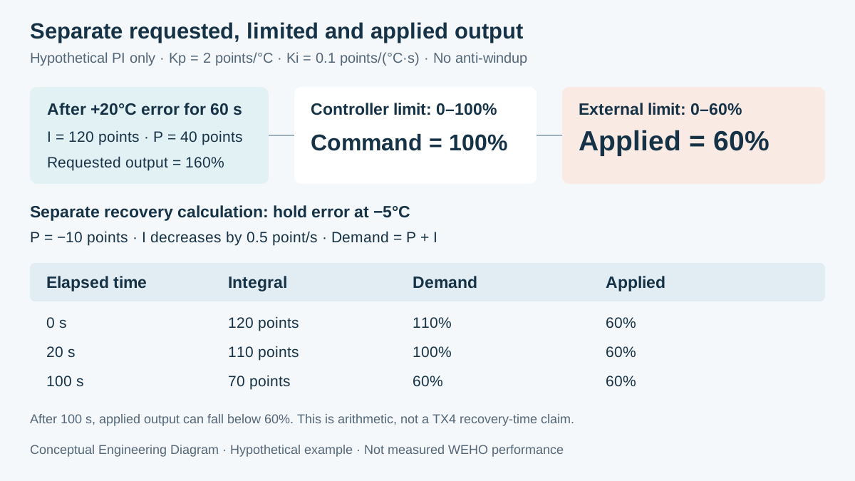
Assume Kp = 2 output percentage points per °C and Ki = 0.1 output percentage points per (°C·s). The controller command is limited to 0–100%, and a separate downstream device restricts applied output to 0–60%. Start with xI = 0 and hold e = +20°C for an illustrative 60 seconds.
The proportional contribution is 2 × 20 = 40 percentage points. The integrator grows at 0.1 × 20 = 2 percentage points per second, reaching 60 points after 30 seconds and 120 points after 60 seconds. Calculated demand therefore grows from 40% to 100% and then 160%, although the actuator cannot exceed 60%.
Now examine a separate hypothetical recovery interval in which e is held at −5°C. Its proportional contribution is −10 points and the integrator decreases at 0.1 × 5 = 0.5 points per second. Beginning from xI = 120, calculated demand initially remains 110%, despite the negative temperature error.
After 20 seconds, xI falls to 110 and calculated demand reaches 100%. Applied output can still remain capped at 60%, because the downstream limit has not changed. Reaching calculated demand of 60% requires xI = 70, which takes (120 − 70) / 0.5 = 100 seconds in this artificial held-error model.
Swipe horizontally on a small screen, or open the full-size diagram.
| Time after error reversal | Integral contribution | Calculated demand | Controller / applied output |
|---|---|---|---|
| 0 s | 120 points | 110% | 100% / 60% |
| 20 s | 110 points | 100% | 100% / 60% |
| 100 s | 70 points | 60% | 60% / 60% |
The example separates command recovery from release of a downstream constraint. It does not define an acceptable overshoot, shutdown time or PID setting. A real process changes its error continuously, so its recovery must be assessed with the actual thermal behavior and applicable performance requirements.
Choose a remedy that can see the actual constraint
An output limiter can protect an operating requirement while leaving the integrator's internal state unresolved. Clamping, back-calculation and tracking use different mechanisms and information. MathWorks' PID controller documentation distinguishes internal limiting from arrangements that account for downstream saturation.
The correct choice depends on what the controller knows and what the actuator actually does. If a limit is imposed elsewhere, confirm whether the selected architecture communicates the effective constraint or applied command. A menu labelled “output limit” alone is not evidence of external tracking or a specific internal integrator policy.
The TX4 series instruction manual establishes the available documented control context, but this article does not derive an anti-windup implementation from its PID designation. Record the ordered revision and obtain relevant behavior information. Avoid editing undocumented parameters to imitate a control method described for different equipment.
The TX4 alarm and external-interlock article addresses another decision: the response to an alarm event. Keep protection design separate from this control-recovery investigation. Improving normal PID recovery does not establish an independent protective function.
Verify recovery with a coordinated operating record
- Map every limiter. Record controller command bounds, downstream power restrictions and any supervisory override. Check the actual signal path against the equipment documentation; do not assume the last displayed percentage equals applied power.
- Capture the operating condition. Record setpoint, measured temperature, command, available actuator feedback and the active limit over a common timebase. Verify timestamp alignment so that communication delay is not mistaken for control-state behavior.
- Establish the documented algorithm scope. Record which limiting, reset, tracking or anti-windup functions are actually specified. Distinguish confirmed settings from unknown implementation details before deciding which remedy the controller can support.
- Define a bounded recovery test. Have the responsible designer select a permitted operating transition and acceptance criteria. Record disturbance, limiter state, output recovery and thermal response without deliberately defeating equipment protection or creating an uncontrolled overtemperature condition.
- Assess the changed arrangement. Compare repeatable records with the original process requirements, including overshoot and settling behavior. Retain the configuration and explanation of the limiting path; a faster output reversal alone does not establish satisfactory temperature control.
Use the same record when a limit is changed or removed during operation. A controller that behaves well at startup may respond differently when a power cap is imposed later. Include the expected transitions in the acceptance plan rather than testing only an unrestricted steady state.
Do not erase the diagnostic evidence by repeatedly changing several tuning parameters together. Identify one supported change, preserve the prior configuration and compare equivalent conditions. The decision should explain why the chosen adjustment addresses the observed constraint rather than merely producing a more attractive trace.
Give WEHO the command and constraint history
Send the TX4-S control behavior enquiry with the complete model label, control mode, relevant settings, downstream limiter description and synchronized operating record. Ask which documented functions apply to that configuration. Request explicit confirmation of any anti-windup or tracking requirement rather than inferring it from the product family name.
Engineering FAQ
Is slow recovery after saturation proof that the SSR failed?
No, slow recovery can occur while an actuator follows its command normally. Compare requested and applied output with the temperature record before assigning a cause. A switching failure and accumulated integral demand require different investigations.
Does a 100% controller limit prevent every windup problem?
No, the result depends on the internal algorithm and any downstream constraints. A separate actuator limit may be lower than the controller's command limit. Confirm what saturation information reaches the controller rather than assuming all limits are equivalent.
Can the 100-second example be used as a TX4 acceptance limit?
No, 100 seconds is calculated from the explicitly assumed held error and integral gain. It is not a measured recovery time or an acceptable thermal delay. Define project limits from the actual equipment requirements and controlled verification.
Does the TX4-S PID label confirm built-in anti-windup?
No, a PID designation does not identify a particular anti-windup implementation. Use the applicable documentation and configuration evidence. If the required recovery behavior is not documented, obtain clarification and verify the complete control arrangement.


