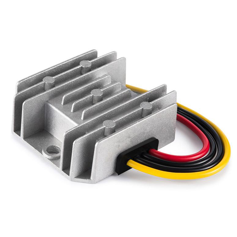
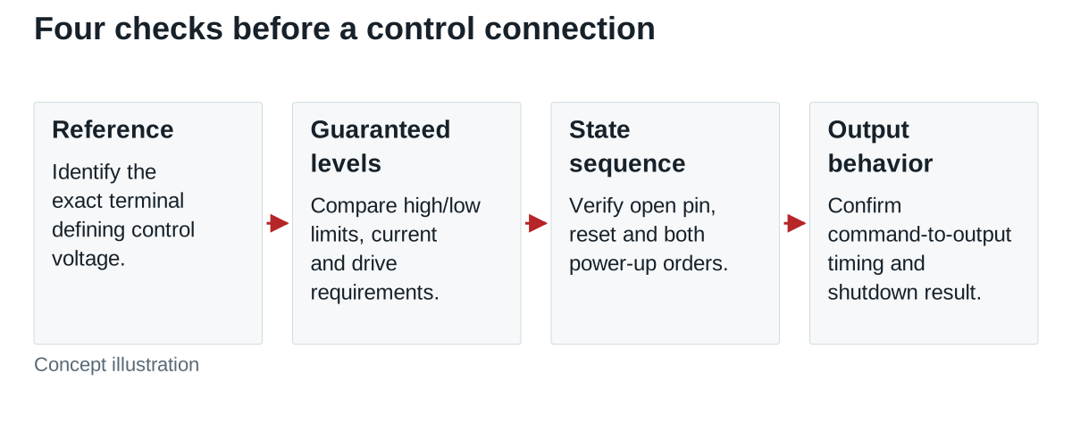
A DC-DC converter’s remote on/off pin is a control interface with its own electrical limits. Before connecting a controller, confirm its reference point, logic option, voltage and current requirements, and default state. A label such as CTRL, EN or ON/OFF does not establish compatibility with a PLC output or a microcontroller GPIO.
On this page
- Build the interface definition from the actual model
- Treat open-circuit behavior as a separate specification
- Compare guaranteed logic levels, not nominal supply names
- Review both power-up orders and shutdown
- Keep shutdown current separate from control current
- Release an interface specification that production can follow
For an OEM interface designer, the decision is whether the complete control path produces the intended state throughout power-up, normal operation and shutdown. Begin with the exact converter ordering code and datasheet revision. Do not infer that a WEHO DC-DC model has remote control, or assign a pin function from another manufacturer’s example.
Build the interface definition from the actual model
Use the pin description, electrical table, application notes and ordering-code options together. If they disagree or leave a limit unclear, resolve the issue before wiring the control. A schematic for another variant can have the opposite logic even when its package looks identical.
The WEHO WH-C241210 provides a concrete document check: its public WH-C241210 specification describes a non-isolated 24 V-to-12 V, 10 A converter and lists three power connections. It does not document a CTRL/EN terminal or remote on/off interface. Do not apply the control connections discussed in this guide to that model without confirming the exact supported function with WEHO.

| Interface field | Question to resolve | Evidence to retain |
|---|---|---|
| Reference point | Which terminal defines control-pin voltage? | Named input-side, output-side or other reference from the exact document |
| Logic and ordering option | Which state enables the converter? | Full part code and high/low truth table |
| Voltage limits | What guarantees low and high, and what must never be exceeded? | Operating thresholds, absolute limits and conditions |
| Current and drive type | What current must the driver sink or source, and is a particular interface required? | Control current, internal bias and approved application circuit |
| Default and sequence | What happens open-circuit, during controller reset and with either device unpowered? | Documented states and power-sequence restrictions |
| Disabled behavior | What stops, what remains energized, and how does output decay? | Shutdown-current and timing definitions, plus system validation |
The control reference deserves its own line in the schematic review. An isolated power output does not prove that its control pin is referenced to that output. The control circuit may belong to the input side. Do not join references simply to make a logic signal work; any required isolation and interface arrangement must follow the actual design requirements.
Treat open-circuit behavior as a separate specification
“Positive logic” and “negative logic” describe the relationship between signal level and enable state. They do not provide a universal rule for a disconnected pin. Internal bias and variant circuitry determine the open-circuit state.
For a concrete manufacturer example, the Murata IRS-Q12 datasheet documents input-referenced remote-control variants with positive and negative logic. In that family, the open-pin states differ by option. It also specifies drive and power-sequence restrictions. These are reasons to check the ordering code, not pin assignments or behavior to copy into a WEHO design.
Define what the equipment should do while its controller boots and its output pins are not yet configured. Then verify that the converter interface actually produces that state. A firmware instruction issued later cannot establish the state during the preceding reset interval.
Compare guaranteed logic levels, not nominal supply names
Consider a hypothetical active-high control input with a guaranteed high requirement of at least 3.0 V and a low requirement of no more than 0.8 V. Suppose a controller powered from a nominal 3.3 V rail guarantees only 2.8 V minimum at its output in the intended load condition.
The high-level margin is 2.8 − 3.0 = −0.2 V, so the high state is not guaranteed compatible. If the same controller guarantees a low output no higher than 0.2 V, the low-level margin is 0.8 − 0.2 = 0.6 V. Passing the low-level check does not rescue the failed high-level check.
These invented thresholds illustrate a comparison; they are not specifications for any converter. The full review must also include control current, voltage tolerance, temperature, signal-reference differences and power sequencing. A nominal “3.3 V compatible” description is insufficient without the guaranteed conditions.
Do not connect an unused control pin to the input supply by assumption. RECOM’s power-supply FAQ notes that allowed control-pin voltage varies by series and directs users to the datasheet. A converter’s permissible power-input voltage is not automatically permissible on its control pin.
Review both power-up orders and shutdown
Check the converter powered while the controller is unpowered, the controller powered while the converter is unpowered, and both rising or falling together. Include resets, loss of communication and any disconnected-control condition required by the equipment specification. The manufacturer may prohibit a voltage on the control pin when converter input power is absent; an apparently valid normal-state logic level does not resolve that condition.
For the approved interface, verify the commanded state against actual output behavior. Capture the command, control-pin voltage relative to its specified reference, output voltage and any readiness status relevant to the equipment. Define delays from command to valid output separately from the output’s rise time.
For shutdown, record whether switching stops promptly, whether the output decays within the required interval and whether other connected circuits can keep the rail energized. Remote disable does not by itself establish a disconnected output or a safe maintenance state. Those requirements need their own documented architecture and verification.
Keep shutdown current separate from control current
RECOM distinguishes current drawn at the power input while disabled from current involved in driving the control pin. Those are different budgets. If low standby energy is a project requirement, record the input-current condition and also account for the controller and interface consumption.
Similarly, an off command does not prove a zero-volt output at a particular time. Output capacitance, connected loads and other sources affect the system result. Use the actual model’s shutdown behavior and the equipment measurements rather than treating “disabled” as a complete electrical description.
Release an interface specification that production can follow
The approved handoff should include the full converter ordering code and revision, reference-point definition, logic table, guaranteed voltage/current compatibility, default state and permitted power sequences. Add the verified control circuit and state-to-output timing limits. Record unresolved conditions as a hold point rather than filling them with a generic connection diagram.
Approve the interface when those conditions are documented and the complete assembly produces the required states. Revise it if a threshold, current or sequence limit is exceeded, or if reset behavior enables the converter unexpectedly.
Send WEHO the exact DC-DC model, controller output stage type (open-drain/collector or push-pull), guaranteed voltage/current levels, required default state and power sequence so the applicable model documentation can be confirmed before a control connection is designed.