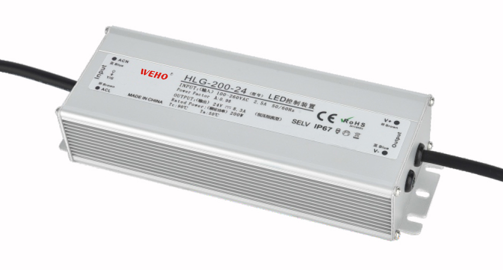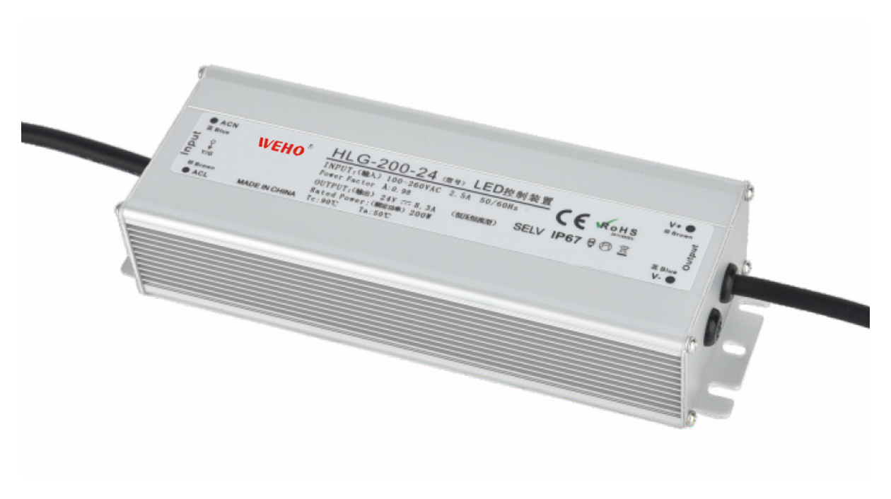
A plant capacitor bank and an active-PFC power supply address different boundaries. A bank can compensate reactive demand at a distribution point; a supply’s PFC function concerns its own AC input behavior. For an OEM choosing a supply, neither a good facility meter reading nor a “PFC” label replaces model-specific PF and harmonic-current evidence at the required operating points.
On this page
- Put the measurement boundary on the request
- Keep PF, displacement and efficiency separate
- A plant arithmetic example is not a bank selection
- Use two evidence requests
- Read a WEHO PF row at its stated condition
- Escalate network questions rather than adding a generic capacitor
- Release the device decision with its conditions
The useful purchasing decision is whether the proposed supply satisfies the equipment’s input requirements, and what separate facility assessment remains necessary. This guide does not select a capacitor bank, specify its installation or establish that WEHO supplies compensation equipment.
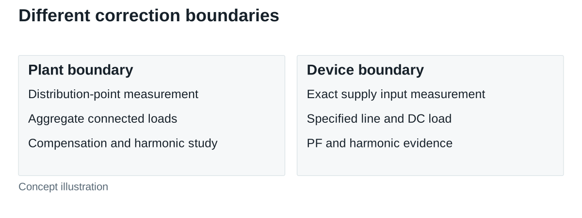
Put the measurement boundary on the request
A distribution-board measurement includes the loads operating behind that meter. An individual supply test concerns one identified unit at a stated line voltage and output load. Combining those records without identifying their boundaries can make a plant-level improvement appear to be a device specification.
Schneider Electric’s reactive-power and harmonic-mitigation overview distinguishes capacitor-bank and harmonic-filtering solutions for installations. That is a facility engineering context. A device supplier should instead identify the exact supply, input conditions, loading and measurement method behind its own performance claim.
Keep PF, displacement and efficiency separate
Texas Instruments’ PFC optimization article defines PF as real input power divided by apparent input power. It also discusses displacement and waveform distortion as separate contributors. An active input stage can shape a converter’s current demand; an external capacitor is not a substitute for evidence about that stage.
Conversion efficiency asks how much input real power becomes useful DC output power. PF asks how real input power relates to RMS volts and RMS amps. Improving one does not numerically establish the other. Keep an efficiency curve, a PF curve and a harmonic-current record as distinct evidence, even when a sales table places them together.
For a hypothetical single-phase operating point, assume measured input power is 180 W, input voltage is 230 V RMS and current is 0.85 A RMS. Apparent power is 195.5 VA and PF is approximately 0.921. These figures do not give efficiency without DC output power, and they do not identify how much of the PF result comes from displacement or distortion.
A plant arithmetic example is not a bank selection
Consider a separate, deliberately simplified sinusoidal example: real demand is 10 kW and inductive reactive demand is 8 kvar. Apparent power is √(10² + 8²), approximately 12.81 kVA, giving PF about 0.781. An idealized 5 kvar capacitive correction would leave 3 kvar net reactive demand: approximately 10.44 kVA and PF 0.958.
The calculation holds real demand constant. It does not show a 10 kW load suddenly consuming less useful energy, determine a capacitor’s capacitance, or model a distorted industrial waveform. Do not apply this triangle as a complete true-PF prediction for a network with substantial harmonics. It is a boundary example, not permission to add capacitance across equipment.
Likewise, a machine that passes a device-level PF test can operate within a facility whose other loads still produce a poor aggregate result. The equipment purchaser and the site electrical engineer need related information, but they are accepting different systems.
Use two evidence requests
| Question | Supply supplier record | Facility engineering record |
|---|---|---|
| Where was performance measured? | Exact model input terminals and test setup | Named distribution point and connected loads |
| Which conditions apply? | Line voltage, frequency, output load and operating mode | Load schedule, bank stages, source and network conditions |
| What does PF mean here? | True PF, displacement information and harmonic data as required | Meter definition, recording interval and aggregate waveform |
| What changes are being accepted? | Supply configuration and equipment input behavior | Compensation equipment and the assessed installation |
Ask for low-load data when the machine spends significant time idle. A full-load point can be valid yet insufficient for the intended duty. Record whether an auxiliary supply, fan or optional board was included. A single PF number without its operating state cannot define acceptance across the equipment’s schedule.
Read a WEHO PF row at its stated condition
The public WEHO HLG-200 specification states PF >0.96 at 230 VAC and full load. That is a documented conditional figure, not a curve across all input voltages and dimmed or idle states. The row alone does not identify the internal PFC controller or qualify an installation’s compensation scheme.
The pictured WEHO HLG-200-24 is the 24 V output variant associated with this family document. Keep that exact identity with the PF condition when requesting device-level input evidence. The published PF row is used here as a conditional device-level record; it does not establish an internal PFC circuit topology.
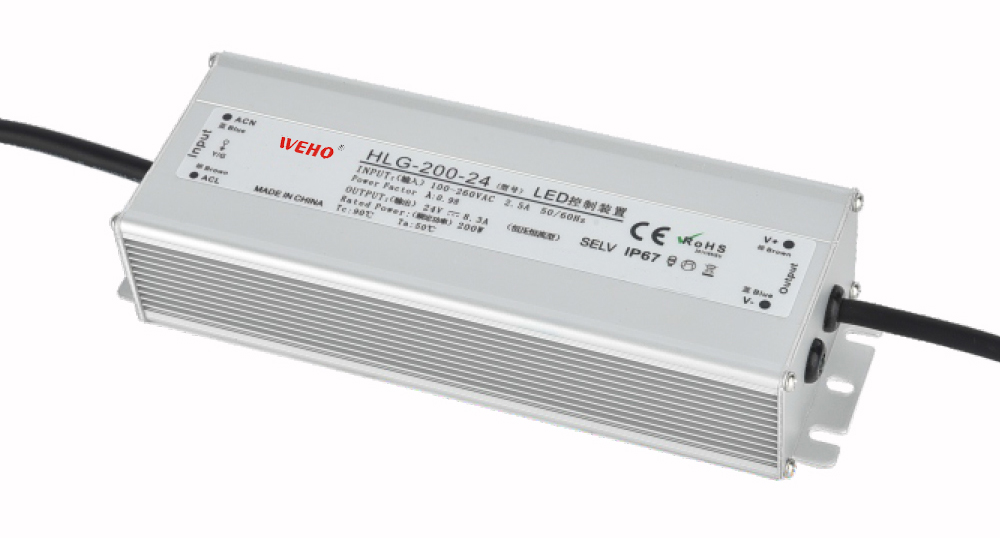
For a proposed model, request the applicable document identity and the conditions your machine actually needs. Do not assume another WEHO family has the same input behavior, or infer harmonic-limit compliance from the PF row. Any applicable equipment-standard assessment belongs to its defined configuration and evidence.
Escalate network questions rather than adding a generic capacitor
Schneider’s overview identifies detuned capacitor-bank solutions for installations containing harmonic energy that could damage standard banks. The practical consequence is to obtain an appropriate network study before a compensation change. A capacitor is not a universal correction for nonlinear input current, and the supply purchasing team should not prescribe a bank from a device’s nameplate watts.
Keep bank switching states and relevant observed voltage events in the site record supplied to the equipment engineer. If equipment behavior changes with compensation switching, reproduce and assess that condition through the responsible specialists; a higher average meter PF is not evidence that every interaction has been resolved.
Release the device decision with its conditions
Accept the supply only against the required input operating points and credible evidence. Hold the affected conclusion when the test boundary, metric or relevant load point is unknown. Keep a plant compensation decision separate, with a responsible site engineer and its own assessment record.
Send WEHO the proposed model, input range, output-load schedule and the PF or harmonic evidence required for the equipment. Include the measurement point and any relevant site power-quality conditions so the model discussion starts from the correct boundary.