



- A floating 24 V output can keep supplying its load after an earth fault; normal DC voltage alone does not prove healthy insulation.
- Choose insulation monitoring for the complete unearthed circuit, including symmetrical deterioration and connected equipment.
- Equal positive-to-earth and negative-to-earth voltages can conceal balanced resistive leakage.
- Define alarm action, fault investigation and restoration separately from the power supply’s output protection.
Define the fault you need to detect
An OEM may intentionally keep a DC control circuit unearthed for a particular system design. A later cable, interface or contaminated device can introduce an unintended connection to the chassis. The load may still receive approximately 24 V, so a DC-OK indication or a routine output measurement need not reveal the change.
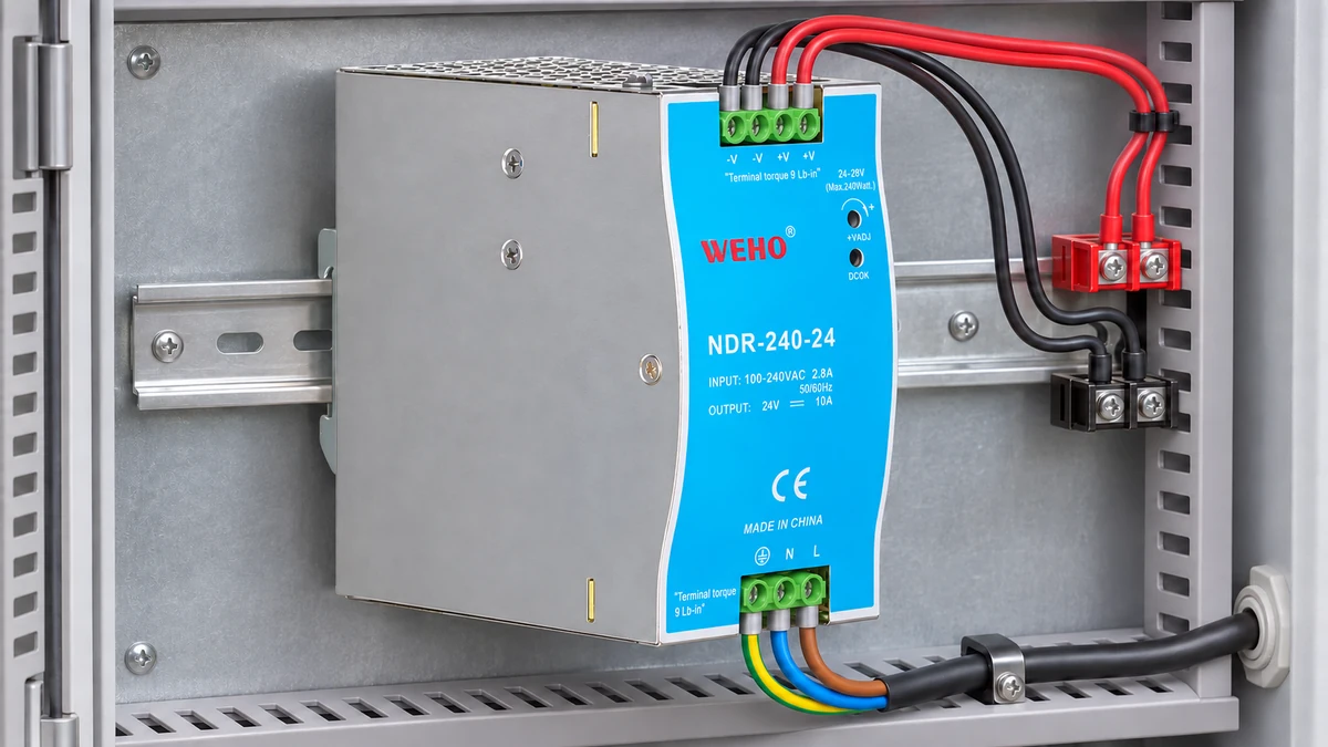
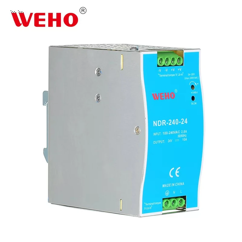
The NDR-240-24 power supply reference provides a concrete model to identify in the equipment record. A 24 V rating does not establish approval for every unearthed architecture, output-to-earth working voltage or monitoring method. Those interfaces require confirmation for the ordered revision and the complete assembly.
What insulation monitoring adds to voltage checks
An insulation monitoring device, or IMD, evaluates insulation resistance between an unearthed circuit and earth. IEC 61557-8:2014 covers devices that permanently monitor this resistance in IT systems. The standard's scope does not by itself select a suitable monitor or establish compliance of a particular machine.
A measurement of positive-to-negative voltage answers whether the differential supply voltage is present. Measuring each pole to earth adds information about reference balance. Neither observation alone establishes a minimum insulation resistance for the whole system, especially when leakage paths exist on both poles.
Bender's insulation monitoring explanation distinguishes asymmetrical and symmetrical deterioration. It also explains why a device relying only on displacement voltage does not provide the same coverage as an appropriate continuous insulation monitoring method. Match the measuring principle to the faults the project must detect.
Keep monitoring and protective action separate
Detection creates information; it does not automatically define the correct machine response. The design may require an alarm, an orderly stop, immediate interruption or another action established by the applicable requirements and risk assessment. Continued operation cannot be authorized merely because this is the first detected fault.
Bender's control-circuit discussion describes how insulation faults can affect control behavior and why monitoring selection needs to address symmetrical faults. Use that engineering context to define the investigation; do not turn it into a generic instruction to keep every faulted machine running.
Calculate why balanced voltages can be misleading
Consider an ideal, isolated 24 V DC source with no intentional pole-to-earth bond. For this hypothetical resistor model, let R+ connect the positive pole to earth and R− connect the negative pole to earth. Ignore capacitance, the measuring device and every other connection so that the arithmetic remains transparent.
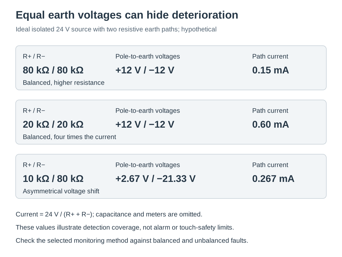
The resistors form a series path across the source through their common earth point. The pole-to-earth voltage magnitudes follow their resistance ratio. With R+ = 80 kΩ and R− = 80 kΩ, the current through that series path is 24 V ÷ 160 kΩ = 0.15 mA, and each pole sits 12 V from earth with opposite polarity.
Now reduce both resistances to 20 kΩ. The current becomes 24 V ÷ 40 kΩ = 0.60 mA, yet the pole-to-earth magnitudes remain 12 V and 12 V. The same voltage balance accompanies a fourfold increase in resistive leakage through the modeled path.
Swipe horizontally on a small screen, or open the full-size diagram.
| R+ / R− | Positive / negative to earth | Series-path current | Observation |
|---|---|---|---|
| 80 kΩ / 80 kΩ | +12 V / −12 V | 0.15 mA | Balanced reference |
| 20 kΩ / 20 kΩ | +12 V / −12 V | 0.60 mA | Worse insulation with unchanged voltage balance |
| 10 kΩ / 80 kΩ | +2.67 V / −21.33 V | 0.267 mA | Asymmetrical reference shift |
The last row follows 24 × 10 ÷ 90 = 2.67 V on the positive pole and 24 × 80 ÷ 90 = 21.33 V on the negative pole. A reference shift can therefore reveal an asymmetry, while absence of that shift cannot rule out balanced deterioration. The calculation illustrates observability, not a procedure for deliberately faulting an operating machine.
Do not apply the ideal model directly to a cabinet reading
Real systems include EMC capacitors, cable capacitance, filter networks and connected instruments. A meter also adds its own path to earth. These features can change transient readings, settling behavior and the result of a particular monitoring technique.
Use the resistor model to challenge a proposed acceptance method: would the method notice both balanced and unbalanced changes? Use the selected monitor's instructions and the actual circuit to establish how that question will be tested. Do not use the example currents to declare touch safety or to set a protective device.
Specify the monitored boundary
A circuit described as floating can become referenced through a USB cable, communication shield arrangement, sensor, test instrument or another power supply. Trace conductive and intentional capacitive paths rather than assuming that a disconnected earth strap is the whole system boundary.
Monitoring requirements should state the circuit voltage, possible external voltages, connected converters, expected leakage capacitance and operating states. They should also identify whether multiple monitors could interact when sections become electrically connected. Resolve such combinations using the manufacturers' instructions rather than connecting several measuring systems by analogy.
| Decisão | Evidências para Record | Acceptance basis |
|---|---|---|
| Unearthed architecture | All bonds, interfaces and source boundaries | Applicable equipment design and supply requirements |
| Fault coverage | Symmetrical and asymmetrical fault cases | Documented measuring principle and project requirement |
| Dynamic behavior | Leakage capacitance, switching states and delays | Selected monitor’s permitted operating conditions |
| Alarm response | Detection, annunciation, action and reset sequence | Equipment risk assessment and functional specification |
| Restoration | Fault location and verified repair record | Approved maintenance and return-to-service procedure |
A monitor's voltage range is only one selection criterion. For example, Bender's isoUG425 product description explicitly identifies asymmetrical insulation monitoring in unearthed DC systems. Read such coverage statements literally; a nominal range that includes 24 V does not prove coverage of symmetrical faults.
Verify coverage and the complete alarm chain
- Map the circuit. Record both DC poles, chassis, connected devices and service interfaces in each operating state. Verify that the intended unearthed boundary actually remains as documented.
- Confirm the measuring method. Record the chosen IMD's fault coverage, supply requirements and permitted system capacitance. Compare those conditions with the real network and the required fault cases.
- Define acceptance before testing. Record project-approved response values, delays and machine actions with their engineering basis. Do not choose thresholds from this article's resistor example.
- Use the approved test procedure. Have qualified personnel record the applied test condition, monitor indication and elapsed response under the equipment's isolation and commissioning controls. Verify the entire alarm path, including the receiving controller or annunciator.
- Check restoration. Record fault clearance, reset behavior and the return-to-service decision. Verify that removing the test condition does not create an undocumented automatic restart or conceal a remaining fault.
The monitor's self-test and an external circuit-coverage test serve different purposes. Record which function each check exercises. A successful display test does not establish that a distant cable section or a separately switched branch is being monitored.
Prepare a supply-interface question for WEHO
Use the NDR-240-24 model and interface page with your network diagram. Send WEHO the intended output-to-earth arrangement and ask about the applicable output interface conditions; review IMD selection and machine fault response with the responsible system designer.
Frequently asked questions
Does a healthy 24 V output prove that no earth fault exists?
No. A floating circuit can retain its differential output voltage while an unintended earth path changes its insulation condition. Evaluate insulation and the alarm requirement separately from normal voltage delivery.
Can two equal pole-to-earth readings rule out insulation deterioration?
No. Symmetrical resistive leakage can preserve equal voltage magnitudes while insulation deteriorates on both poles. The monitor's measuring principle must cover the fault cases the design requires.
Does a first earth-fault alarm always allow continued operation?
No. The permitted response depends on the equipment requirements, risk assessment and protective design. Define the required alarm action and repair process before commissioning the monitored system.
Is a monitor suitable just because its range includes 24 V?
No. Check its measuring principle, symmetrical-fault coverage, system-capacitance limits, connected equipment and alarm behavior. Supply voltage compatibility alone is insufficient to select the complete monitoring arrangement.



