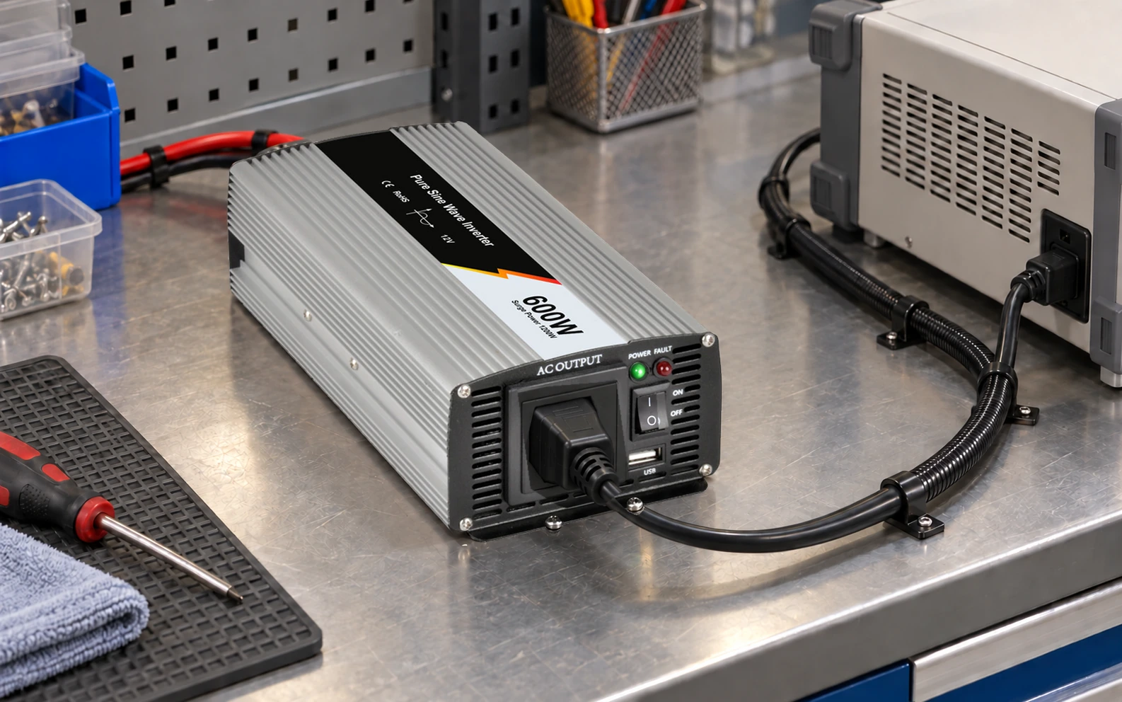
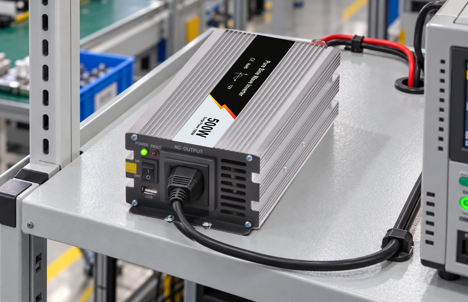
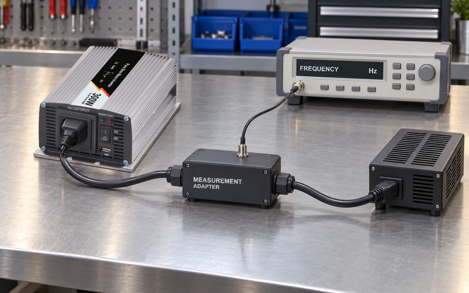
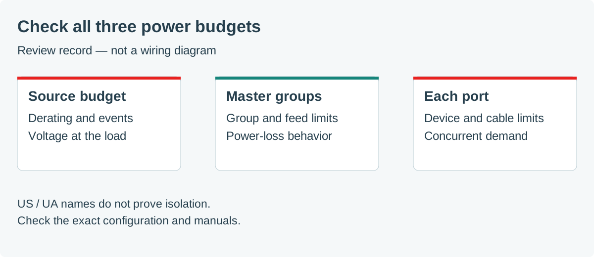
Size an IO-Link installation from three budgets: the upstream supply, the master’s input groups and each individual port. Map system and actuator power using the exact master and device manuals, then check simultaneous current, voltage at the devices and the required behavior when one group loses power. A larger 24 V power supply cannot increase a master’s port or group limit.
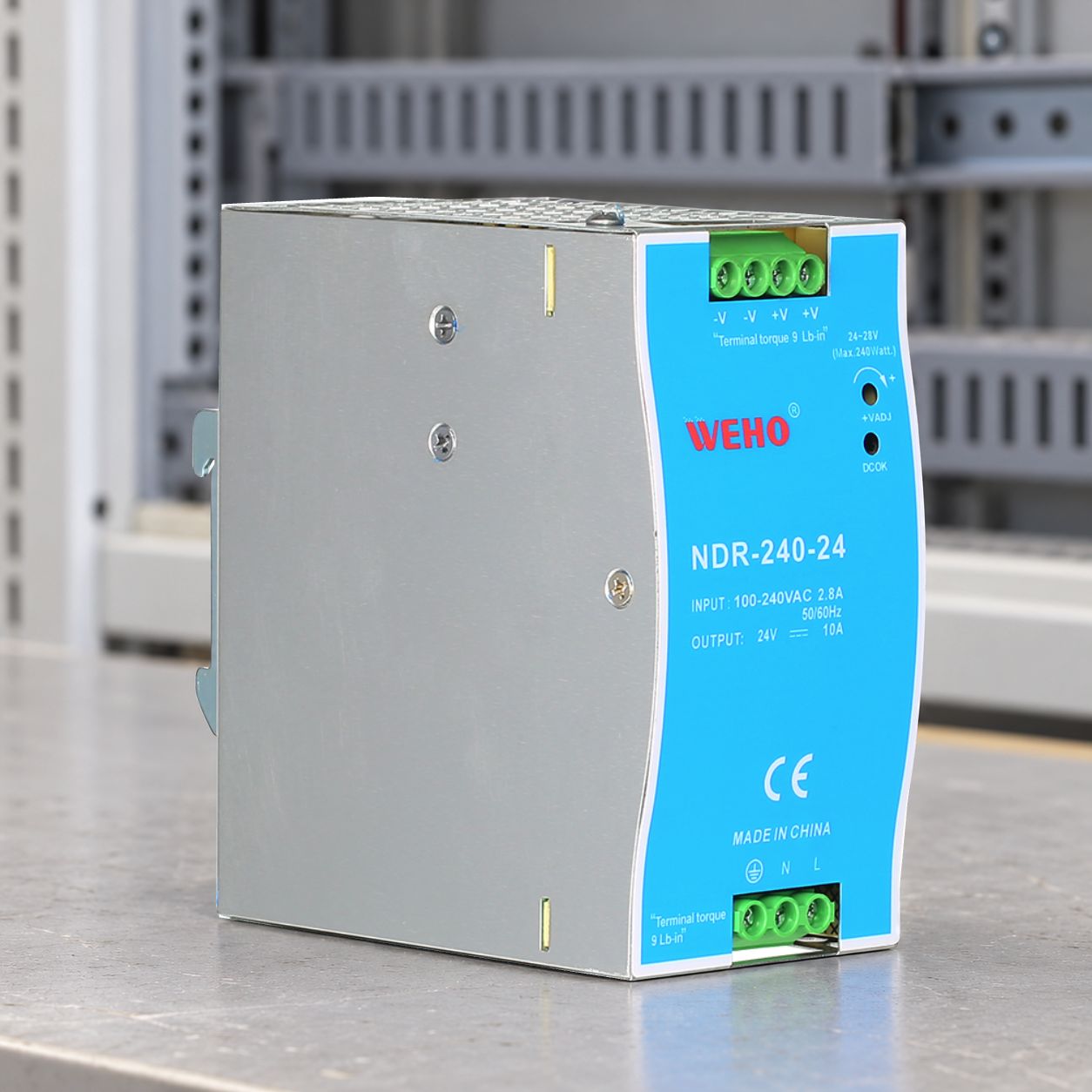
This guide helps an equipment engineer build a power worksheet before ordering the supply and master. It is not an IO-Link communication tutorial. The useful output is a traceable port-and-group record, including the states that the machine must survive.
Map system and actuator power
Class A and Class B describe different IO-Link port power arrangements. ifm’s explanation of A and B ports distinguishes the usual device supply from additional power used by higher-demand output devices. Its particular product current examples must not become universal limits.
List what each connection actually supplies: master electronics, device electronics, sensors connected through an I/O module, actuator outputs and any loop-through feed to another master. Names such as US e UA are useful when the manufacturer defines them, but they are not a substitute for that model’s power diagram.
For a design using the Class B interface in IO-Link Interface and System Specification V1.1.4, §5.4.2, review its Power 1/Power 2 isolation and power-loss requirements together with the declared master/device configuration. Do not join returns or assume isolation merely because two terminals have different supply names. Check each connected device’s documented isolation and return paths in the intended configuration, and resolve any conflict with the required Power 1/Power 2 separation before connection.
Read port and group limits separately
A device may be within its own port limit while several devices exceed a shared group limit. Supply and loop-through connectors can add another constraint. Record each limit with its temperature, connector and configuration conditions. Check whether the manufacturer’s stated input consumption already includes the field loads, so the worksheet neither omits nor double-counts them.
For example, ifm’s AL1400 product data separates actuator-supply total current from per-port current and lists configurable port limiting. That layout demonstrates why one headline current number is insufficient. The values and settings for that model are not ratings for every IO-Link master.
On small screens, scroll sideways to read all three budget levels.
| Budget level | Record from the exact documentation | Decision it controls |
|---|---|---|
| Upstream source | Usable output at cabinet conditions, current-limit behavior and allowed distribution. | Whether the source can support the intended operating events. |
| Master input/group | Electronics demand, field-load total, connector and loop-through limits. | Whether the shared path supports concurrent ports and downstream modules. |
| Each port | Configured limit, device running/startup current and cable conditions. | Whether one device may be connected and started on that port. |
Check an illustrative simultaneous-load budget
The following is a hypothetical 24 V worksheet, not an NDR rating or an approved master configuration. Assume 0.20 A for master electronics and four sensors at 0.12 A each on the system-power group. The system-group subtotal is 0.20 + 4 × 0.12 = 0.68 A, before any other loads or distribution losses.
Separately, assume three actuators each draw 0.60 A while holding and 1.50 A during pickup. Suppose the selected configuration permits 2.00 A per relevant port and 4.00 A for the actuator group. Holding demand is 3 × 0.60 = 1.80 A, while concurrent pickup is 3 × 1.50 = 4.50 A.
Each 1.50 A pickup is below the assumed 2.00 A port limit, but 4.50 A exceeds the assumed 4.00 A group limit. Installing a source with a higher current rating does not remove that restriction. Review another documented configuration or a permitted operating sequence with the equipment designer. If timing is used, include overlaps, restart and fault recovery rather than assuming the normal sequence always applies.
At nominal 24 V, the illustrative actuator group represents 43.2 W holding and 108 W during the stated pickup event. Those powers describe the example load; they do not determine source transient capability, allowable duration or isolation architecture. Retain the current-versus-time requirements beside the arithmetic.
Define the power-loss states
Write the expected behavior with system power present and actuator power removed, then with the reverse condition, both removed and each restored. Identify communication availability, the validity of sensor data, output behavior and the required restart sequence. A link that continues communicating does not prove that every attached sensor remains powered.
ifm’s IO-Link module guidance specifically warns that some B-port-powered modules supply their sensors from UA along with actuators. Removing UA can therefore remove those sensors too. Review the actual module’s power arrangement instead of applying the expectation from a different product.
On small screens, scroll sideways to compare the required power-loss behavior.
| State | Questions for the selected equipment | Evidence to retain |
|---|---|---|
| System on, actuator off | Which electronics and sensors remain powered? What diagnostics remain valid? | Manual power paths and observed communication/data behavior. |
| System off, actuator on | What output state is permitted? Can another interface backfeed? | Manufacturer restrictions and defined machine response. |
| Both off | What energy or signals can remain at interfaces? | Equipment power-down and maintenance requirements. |
| Power restored | What starts first, and can several outputs demand current together? | Controlled restart sequence and voltage/current records. |
This is a functional integration record. Separating supply groups alone does not establish a safety function or a safety rating. Any required protective shutdown needs the appropriate system design and verification.
Qualify the source and distribution
After the port and group checks, assess the upstream supply at the actual installation temperature and load profile. Compare voltage at the supply, master input and relevant device during the same event. Include cable and connector drop, distribution protection and any permitted daisy chain. A nominal voltage measured at an unloaded supply does not qualify the remote port.
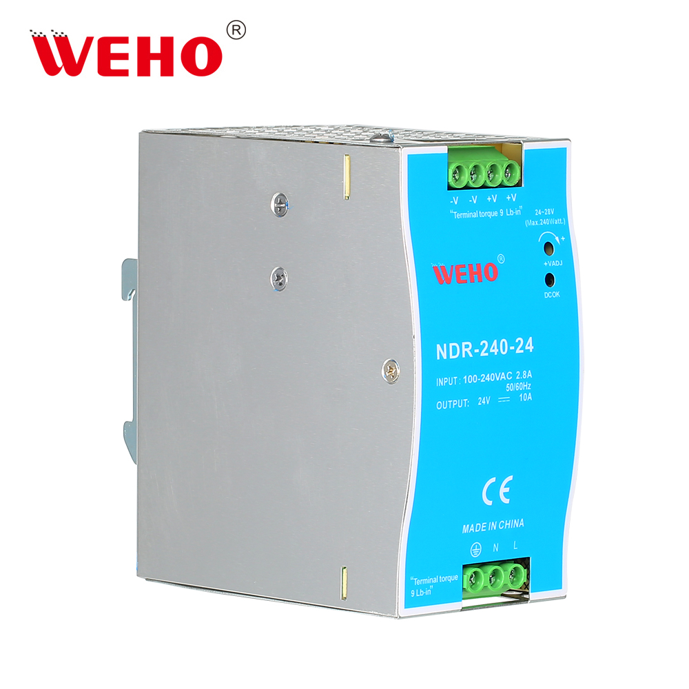
The broader PLC, sensor and solenoid load-budget guide covers machine branches. Here, preserve the additional master and per-port constraints. A failure at one of those levels needs a targeted correction rather than a larger supply selected without explanation.
Send a complete power worksheet
Keep one row per connected device, its assigned port/group, documented steady and starting current, simultaneous-event assumptions and acceptable device-terminal voltage. Add the exact master configuration, source revision and the loss-state table. Mark a missing limit as a question for the supplier, not as spare capacity.