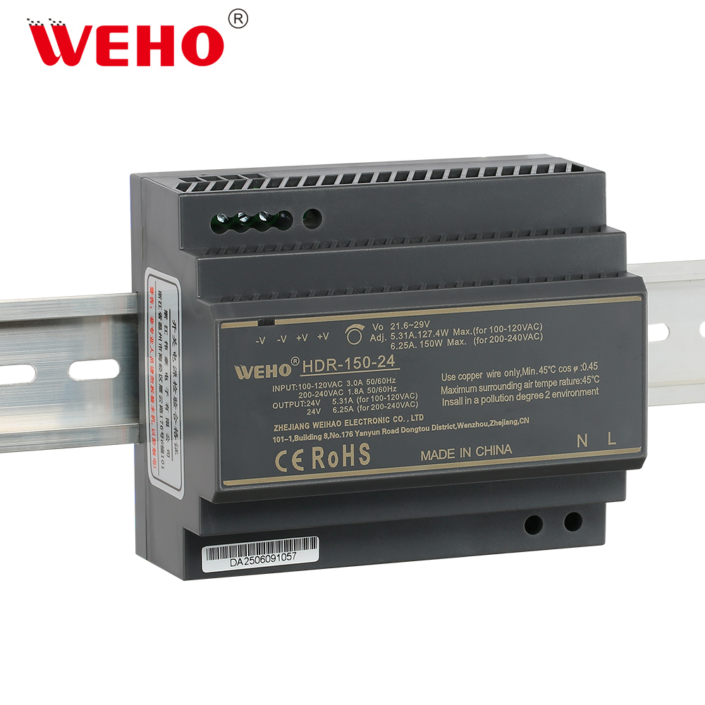
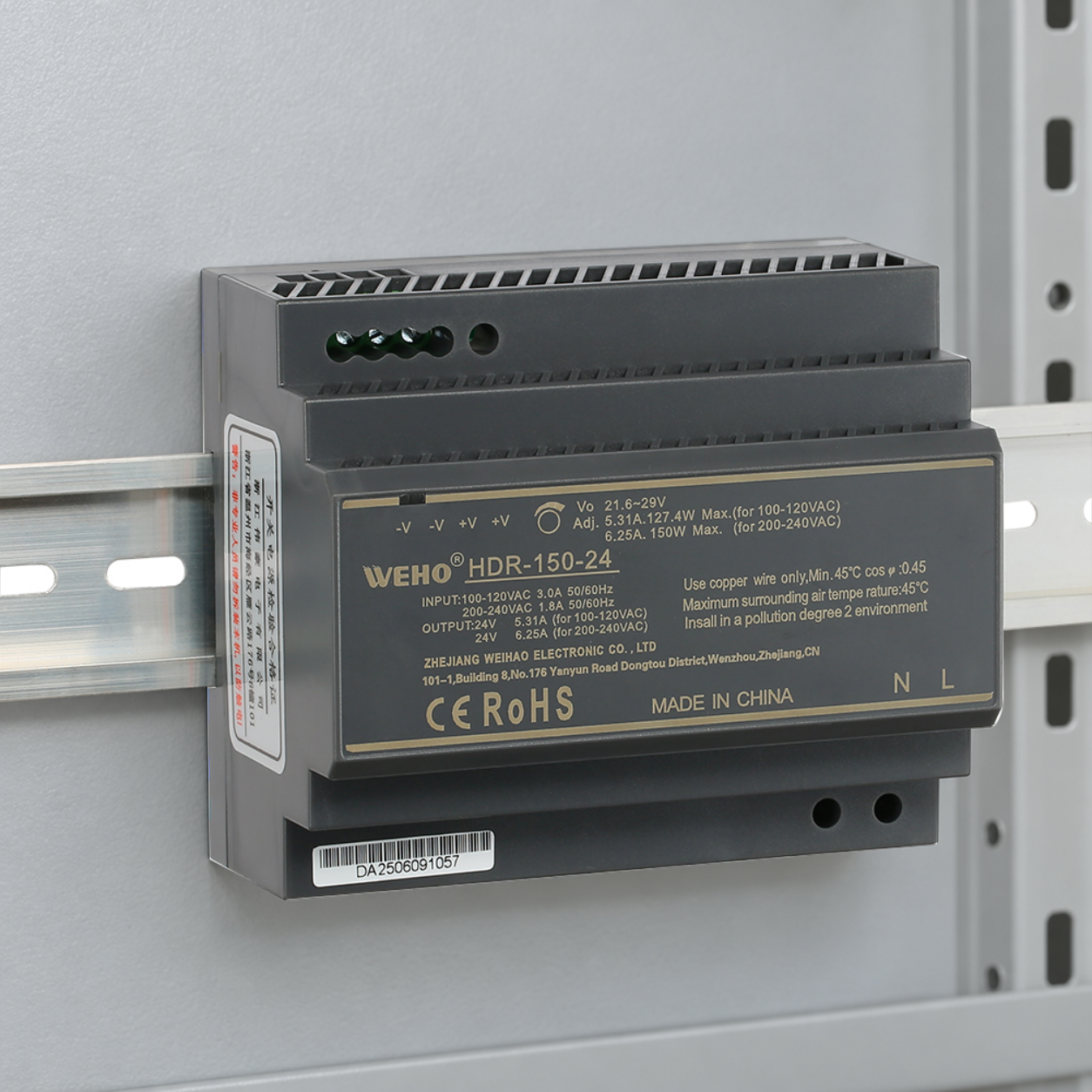
For one 24 V DIN rail power supply BOM used in both 115 V and 230 V equipment, compare the documented output capability at each input condition before approving a common part. A broad AC input range says which supply conditions the unit accepts. It does not necessarily promise the same output current throughout that range.
On this page
This is a release task for an export-equipment engineer or buyer: can the same identified assembly support the same controlled load in both market configurations? Keep the input-conditioned current table with the BOM instead of relying on the wattage in the series name.
Read the two rows for the exact output variant
ที่ WEHO HDR-150-24 illustrates the document check. In the publicly linked HDR-1502.pdf specification, its 24 V column lists 0–5.31 A at 115 V AC และ 0–6.25 A at 230 V AC. Those two entries must remain associated with their stated input conditions.
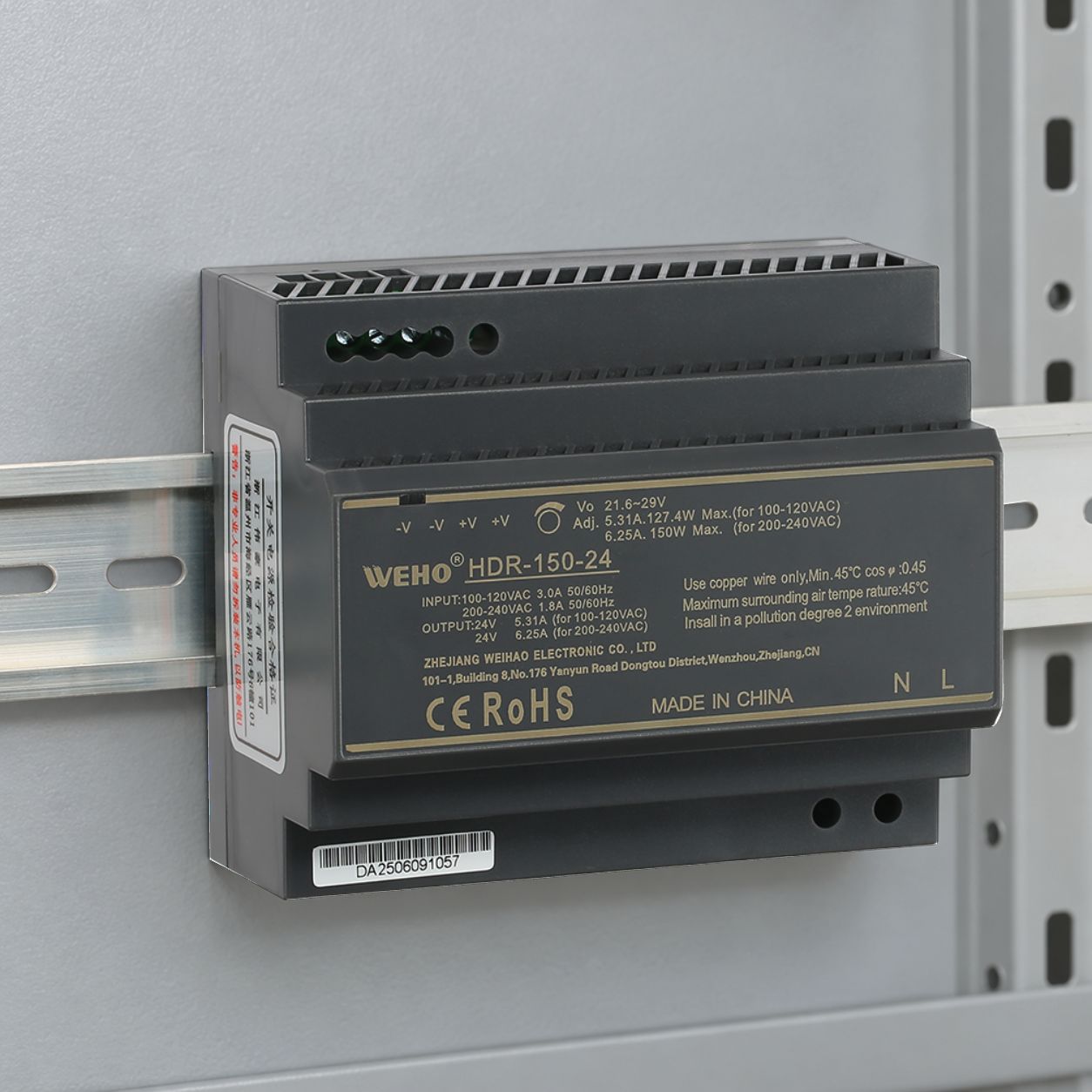
The photographed nameplate also marks 5.31 A, 127.4 W max. for 100–120 VAC และ 6.25 A, 150 W max. for 200–240 VAC. HDR-1502.pdf presents its current rows at the nominal 115 V AC and 230 V AC checkpoints. Keep each source’s stated input conditions with its entry; a photograph does not replace the applicable specification or fill gaps between documented operating conditions. If a delivered label, quotation or another revision states a different current or ambient limit, obtain clarification for that exact assembly before release. Do not choose whichever document gives the larger number.
Test a common load against both entries
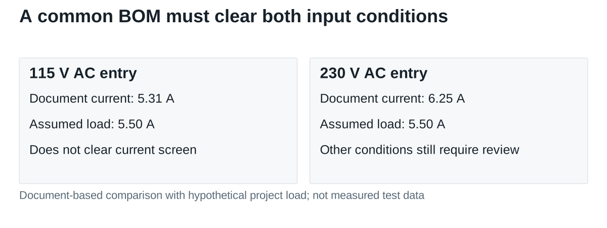
Hypothetical project example: an equipment design requires a maximum simultaneous steady current of 5.50 A at 24 V, or 132 W. Assume that this is the complete load budget before checking startup, temperature or other limits. This figure is an example requirement, not a test result or a rating assigned to the product.
| Input condition in HDR-1502.pdf | Listed 24 V output current | Comparison with the assumed 5.50 A load |
|---|---|---|
| 115 V AC | 5.31 A | Load exceeds the entry by 0.19 A, equivalent to 4.56 W at 24 V |
| 230 V AC | 6.25 A | Arithmetic difference is 0.75 A, equivalent to 18 W at 24 V |
On this document basis, the 115 V configuration fails the initial current screen. The 230 V configuration clears only that screen; the 0.75 A difference is not a general reserve or proof of thermal suitability. Consequently, the assumed 5.50 A equipment load cannot be approved for both configurations by citing this table alone.
At 24 V, the 115 V entry corresponds to 24 × 5.31 = 127.44 W, while the 230 V entry corresponds to 150 W. These calculations explain why the series’ 150 W description cannot be treated as an unconditional output allowance. The article does not infer a current limit at an unlisted intermediate input voltage.
Choose the BOM action before ordering common stock
There are several possible responses to a failed input-condition screen. Engineering could reduce the controlled load if the equipment requirements allow it, review a different candidate with documented capability at both inputs, or maintain separately qualified configurations. The decision belongs in the release record; purchasing should not create it by accepting a higher-wattage description in a quotation.
If one common source is still the goal, request the maximum permitted continuous current over the project’s actual AC range, temperature and mounting conditions. Identify any required settings or installation restrictions. A general statement that a unit operates on both market voltages does not close an output-capability question.
Carry the same conditions into sample validation
Define the source conditions at the power supply terminals, including the relevant normal input extremes for each equipment configuration. A nominal 115 V bench test and a nominal 230 V test are useful checkpoints, but do not by themselves cover all permitted supply conditions. Use the manufacturer’s confirmed operating envelope to choose the remaining points.
Retain the assembled enclosure, mounting orientation, nearby heat sources and load state in the record. Record startup and the equipment’s required sequence separately from continuous-current capability. A successful room-temperature start does not resolve the maximum sustained load in a closed cabinet.
| Common-BOM evidence | Required association |
|---|---|
| Identity | Exact model, delivered assembly revision, nameplate and controlling specification |
| Electrical envelope | Each market’s AC conditions and maximum simultaneous DC demand |
| Installation envelope | Mounting, cooling conditions, ambient assumptions and permitted current |
| Validation | Test configuration, observations and disposition for each market variant |
Keep the incoming check tied to the approved configuration
Give receiving inspection the identity and document references used in the decision. An exterior similarity or unchanged family name is insufficient if the source revision or input-dependent rating changes. Keep any manufacturer clarification with the approved part record so the next buyer does not reopen the same ambiguity.
Ask WEHO to review your 115 V and 230 V load matrix with the proposed HDR-150-24 revision. Include the complete current schedule and installation conditions. Request an identified capability record before deciding whether a shared BOM or separate qualified configurations are appropriate.