



Screen a 24 V to 12 V converter against the normal load and intended running-load pulses, then qualify its overload and recovery behavior separately. A 10 A output rating does not define its current-limit threshold, and automatic recovery does not define a recovery time. The required outcome is a source and load combination that meets the equipment’s voltage and functional limits.
This distinction matters when the equipment remains connected during a fault or must recover without a manual power cycle. A larger rating may remove one continuous-load constraint, but it does not prove that the voltage stays inside the load’s limits during a fast current change.
Article sections
Describe normal load, overload and a short separately
Write the required voltage and current for normal running, an intended load pulse and a fault. A normal pulse is a load requirement to support; a short circuit is an abnormal condition to contain. Do not merge them into a single maximum-current number.
| สถานะ | Question to answer | Evidence needed |
|---|---|---|
| Continuous running | Can the converter supply the load at the actual input and mounting conditions? | Applicable output rating and thermal conditions |
| Running-load pulse | What voltage excursion and recovery occur at the required current and slew rate? | Defined dynamic test with the intended wiring |
| โอเวอร์โหลด | Does the output limit, reduce, retry or latch off? | Model-specific characteristic and recovery behavior |
| Output short | What current flows, for how long, and what happens after removal? | Fault-current record and acceptance procedure |
The acceptance limits belong to the equipment. For example, a controller may tolerate a brief voltage change but must not reboot, while another load may require a controlled reset. Define that behavior before choosing the module or setting a test duration.
Compare the published WH-C241205 and WH-C241210 evidence
ที่ WH-C241205 24 V to 12 V converter และ WH-C241210 24 V to 12 V converter are non-isolated references with different published output ratings. Their documents also describe protection differently.
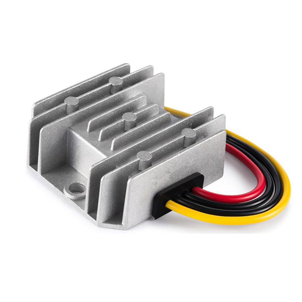
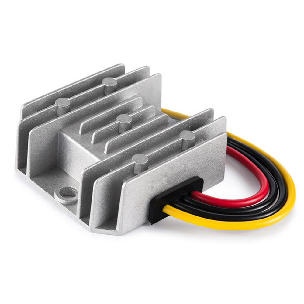
| Published item | WH-C241205 | WH-C241210 |
|---|---|---|
| Rated 12 V output | 5 A / 60 W | 10 A / 120 W |
| Overcurrent description | PDF: 5.3 A ±0.25 A, constant-current mode, automatic recovery | Above 120% of rated current; automatic recovery after overcurrent disappears |
| Short-circuit description | Maximum 5 A at 0 V | Maximum 5 A at 0 V |
| Recovery timing or complete curve | Not established by the reviewed public document | Not established by the reviewed public document |
Sources: the WH-C241205 specification และ WH-C241210 specification. The 5 A model’s webpage writes the tolerance with a plus sign, while its PDF gives ±0.25 A. Resolve the applicable revision before treating that band as a controlled limit. The reviewed PDFs do not display a clear revision identifier.
For the 10 A model, the 120% wording must not be converted into a guaranteed 12.0 A trigger with a known tolerance or delay. Likewise, identical short-circuit current statements do not establish identical thermal stress, restart sequence or fault-clearing performance.
Request a complete output voltage–current characteristic and the corresponding recovery record, including the residual load after a fault is removed. An overload description and a short-circuit endpoint are not enough to identify the internal control mode or predict the path back to 12 V. Evaluate recovery with the actual load behavior, including constant-power demand where applicable.
Screen a 4 A running load with a 6 A pulse
Use this hypothetical requirement: a 12 V load runs at 4 A, then requests an additional 2 A for 20 ms before returning to 4 A. The event starts after the equipment has reached normal operation. It is not a capacitive-startup calculation or a measured WEHO waveform.
| Required state | Calculation | Required output |
|---|---|---|
| Before the pulse | 12 V ×4 A | 48 W |
| During the 20 ms pulse | 4 A +2 A; 12 V ×6 A | 6 A / 72 W |
| Energy delivered during the pulse at the target voltage | 72 W ×0.020 s | 1.44 J |
| Additional energy above the running load | 12 V ×2 A ×0.020 s | 0.48 J |
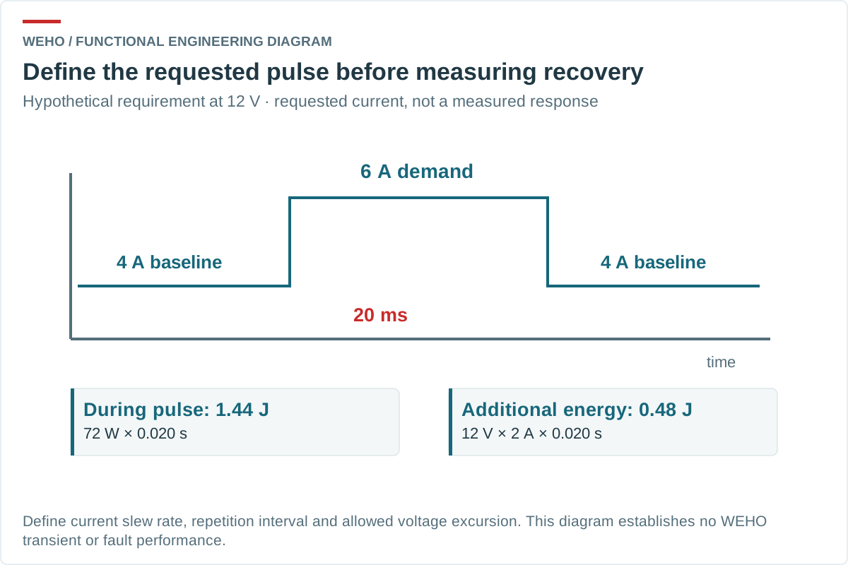
The 6 A requirement exceeds the 5 A model’s output rating. A short duration does not create permission to use it as a 6 A source. The 10 A model clears that current-rating screen, but the table does not prove its transient voltage or operating temperature. Confirm those separately at the intended input and installation.
Use the 0.48 J as the additional load energy over the 20 ms event, not automatically as an external capacitor requirement. The converter may supply some or all of it. If a buffer is proposed, assess the remaining energy shortfall, allowed voltage droop, capacitor losses and the converter’s permitted output capacitance and stability conditions. State the minimum acceptable load voltage and recovery time when requesting a step-response review.
Specify the pulse repetition interval and the allowed voltage range as well. Two loads with the same 6 A peak can present different average heating and control demands when one pulses occasionally and the other repeats continuously. Keep the requested pulse shape separate from any response later measured.
Turn automatic recovery into an acceptance sequence
Begin with the rated load and record a controlled transition into the agreed overload. Capture output voltage and current together, then remove the overload without changing unrelated conditions. Record how the source and load return to the required state.
| Recovery item | What the record should say |
|---|---|
| Protection mode | Continuous limiting, reduced-current behavior, repeated restart or another documented response |
| Removal of the overload | Required residual load, external intervention and any power-cycle condition |
| Return to acceptable voltage | Start event, voltage threshold, time limit and overshoot limit |
| Equipment function | Whether communication, state retention and controlled restart meet the project requirement |
These are possible descriptions to distinguish, not modes assigned to either product without evidence. An automatic output restart can still reboot the connected equipment or cause repeated attempts into a persistent fault.
Validate the source, branch and load as a combination
Keep the actual upstream source, output harness, connectors and protective devices in the representative setup. Document source-current limiting so it is not mistaken for the converter’s own behavior. Measure at both the converter output and the load if cable loss could affect the conclusion. Where continuous heat loss affects suitability, compare efficiency measurements at defined DC boundaries separately; an efficiency point does not establish overload recovery.
A fuse or breaker must be evaluated against the available current and its own DC ratings. A module’s short-circuit statement does not establish selectivity or a clearing time. Use an agreed, suitably controlled fault fixture and limits for duration and temperature; do not repeatedly short an undocumented assembly to infer a rating.
Retain separate results for intended load pulses and abnormal faults. If the load has reset, the current demand after recovery may differ from the demand before the fault. That can make a bench result appear stable while the real equipment repeatedly restarts.
Request the model-specific recovery evidence
Release the chosen current rating together with an overload requirement, a fault-removal condition and a functional recovery criterion. This gives procurement and incoming inspection a specific configuration to preserve.
Send WEHO the 12 V load and recovery requirement with the running current, pulse amplitude and timing, allowed voltage range, input range and intended fault protection. Request the applicable model revision and the protection information needed to review that combination.




